


MPC563XM Reference Manual, Rev. 1
Freescale Semiconductor
701
Preliminary—Subject to Change Without Notice
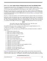
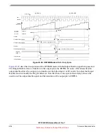
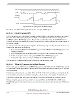
Figure 22-71. OPWMT with 100% Duty Cycle
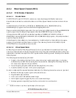
22.5.1.2
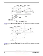
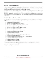
Input Programmable Filter (IPF)
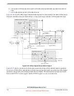
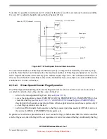
The IPF ensures that only valid input pin transitions are received by the Unified Channel edge detector. A
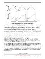
block diagram of the IPF is shown in
.
The IPF is a 5-bit programmable up counter that is incremented by the selected clock source, according to
bits IF[0:3] in EMIOSC[n] register.
Figure 22-72. lnput Programmable Filter Submodule Diagram
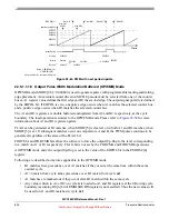
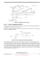
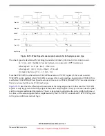
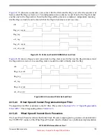
The input signal is synchronized by system clock. When a state change occurs in this signal, the 5-bit
counter starts counting up. As long as the new state is stable on the pin, the counter remains incrementing.
If a counter overflows occurs, the new pin value is validated. In this case, it is transmitted as a pulse edge
to the edge detector. If the opposite edge appears on the pin before validation (overflow), the counter is
reset. At the next pin transition, the counter starts counting again. Any pulse that is shorter than a full range
of the masked counter is regarded as a glitch and it is not passed on to the edge detector. A timing diagram
of the input filter is shown in
$0011FF
$001000
$000000
selected counter bus
Time
output flip-flop
A1 value
1
write to B2
$000400
B1 value
B2 value
2
$001200
Match B1 does not occur
write to A1
$xxxxxx
$000400
$001000
and B2
$001000
Match A1
Match B1
Match A1
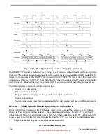
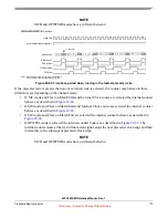
Notes: 1. EMIOSA[n] = A1
2. EMIOSB[n] = B2 for write, B1 for read
$001200
Notes:
A2 value $000500
$000500
FLAG pin/register
Match A2
Match A2
IF3
filter out
ipg_clk
Prescaled Clock
IF2
IF1
IF0
clk
FCK
EMIOSI
5-bit up counter
synchronizer
clock


