


MPC563XM Reference Manual, Rev. 1
Freescale Semiconductor
1277
Preliminary—Subject to Change Without Notice
DATA — Data Field
Up to eight bytes can be used for a data frame. For Rx frames, the data is stored as it is received from
the CAN bus. For Tx frames, the CPU prepares the data field to be transmitted within the frame.
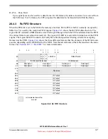
28.4.3
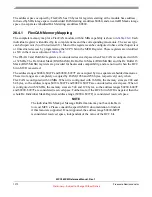
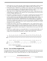
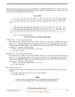
Rx FIFO Structure
When the FEN bit is set in the MCR, the memory area from $80 to $FF (which is normally occupied by
MBs 0 to 7) is used by the reception FIFO engine.
shows the Rx FIFO data structure. The
region $0-$C contains an MB structure which is the port through which the CPU reads data from the FIFO
(the oldest frame received and not read yet). The region $10-$DF is reserved for internal use of the FIFO
engine. The region $E0-$FF contains an 8-entry ID table that specifies filtering criteria for accepting
frames into the FIFO.
shows the three different formats that the elements of the ID table can
assume, depending on the IDAM
field of the MCR. Note that all elements of the table must have the same
format. See
for more information.
0
3
4
7
9
1
0
1
1
1
2
1
5
1
6
2
3
2
4
3
1
$0
S
R
R
I
D
E
R
T
R
LENGTH
TIME STAMP
$4
ID (Standard/Extended)
ID (Extended)
$8
Data Byte 0
Data Byte 1
Data Byte 2
Data Byte 3
$C
Data Byte 4
Data Byte 5
Data Byte 6
Data Byte 7
$10
Reserved
to
$DF
$E0
ID Table 0
$E4
ID Table 1
$E8
ID Table 2
$EC
ID Table 3
$F0
ID Table 4
$F4
ID Table 5
$F8
ID Table 6
$FC
ID Table 7
= Unimplemented or Re-
served
Figure 28-3. Rx FIFO Structure


