


MPC563XM Reference Manual, Rev. 1
Freescale Semiconductor
1263
Preliminary—Subject to Change Without Notice
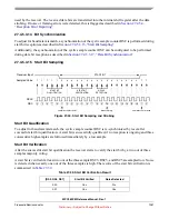
NOTE
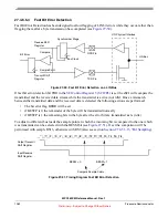
To calculate the exact position of the sample point with regard to the RX pin,
the delays through the pads and the two Bus Clock cycle delay through the
input synchronizer also needs to be taken into account.
27.4.6.5.5
Slave Timeout Detection
A slave timeout is detected, when the LIN slave has not transmitted all requested data bytes of an LIN RX
frame within the amount of timeout specified in the TO[11:0] field in the LIN RX frame control data. The
timeout period starts with the transmission start of the LIN break character and is specified in multiples of
the bit time.
If the last data byte is not received within the specified amount of time, the STO flag in the
will be set.
According to LIN 1.3 the timeout value TO has to be set to
Eqn. 27-11
If the LIN debug mode bit LDBG in the
LIN Control Register 1 (LINCTRL1)
is not set, the transmission
is aborted and the transmitter and receiver are reset.
27.4.6.5.6
Checksum Error Detection
If the checksum enable bit CSE in the
LIN TX Register (LINTX) - RX frame
checking is performed based on the received checksum byte. The checksum mode is selected by the CSM
bit in the
LIN TX Register (LINTX) - RX frame
. If the value received in the checksum bytes did not match
the calculated checksum, the checksum error flag CKERR in the
LIN Status Register 1 (LINSTAT1)
will
be set.
27.4.6.5.7
CRC Error Detection
The CRC checking is performed on the two received CRC bytes CRC1 and CRC2 if the CRC Enhanced
LIN frame format was selected by the CRC bit in the
LIN TX Register (LINTX) - RX frame
received in the two CRC bytes did not match the calculated CRC pattern, the CRC error flag CERR in the
LIN Status Register 1 (LINSTAT1)
will be set.
27.4.6.5.8
Overflow Detection
When the receiver has received the next byte field, which should be transferred into the
, but neither the application nor the RX DMA channel have read data from this register since the
last update, the received data overflow flag OVFL in the
LIN Status Register 2 (LINSTAT2)
will be set.
In this case the content of the
is not changed. The data received most recently
are lost.
27.4.6.6
LIN Wakeup
The section describes the LIN Wakeup behavior of the eSCi module.
TO
10 LEN
45
+
⋅
(
)
(
)
1.4
×
=
LEN is the number of data bytes in the frame
)
(


