


MPC563XM Reference Manual, Rev. 1
Freescale Semiconductor
1241
Preliminary—Subject to Change Without Notice
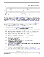
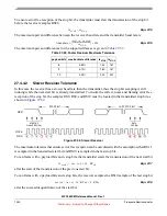
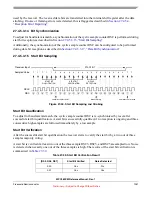
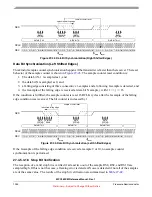
To ensure error free reception of the last stop bit, the transmitter must start the transmission of the start bit
after the receiver samples RS10.
Eqn. 27-9
The maximum percent difference between the receiver baud rate and the transmitter baud rate is:
Eqn. 27-10
The maximum percent differences for the supported frames is given in
27.4.5
SCI Mode
27.4.5.1
SCI Mode Configuration
The application must configure the following bits and fields in order to achieve correct SCI operation.
•
enable
SCI
Mode
–
LIN Control Register 1 (LINCTRL1)
[LIN]:= 0
•
select
baud rate
–
SCI Baud Rate Register High (SCIBDH)
SCI Baud Rate Register Low (SCIBDL)
•
select
receiver input
mode
–
SCI Control Register 1 (SCICR1)
–
SCI Control Register 1 (SCICR1)
•
select
frame format
–
SCI Control Register 1 (SCICR1)
–
SCI Control Register 1 (SCICR1)
[PE]
–
SCI Control Register 1 (SCICR1)
[WAKE]
–
SCI Control Register 5 (SCICR5)
•
select
parity type
–
SCI Control Register 1 (SCICR1)
[PT]
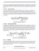
27.4.5.2
Transmitter
The transmitter supports the transmission of all frame types defined in
, of all break characters
defined in
, and of all idle characters defined in
Table 27-31. Slower Receiver Maximum Tolerance
payload bits stop bits max baudrate difference rx
STOP
tx
START
8
1
4.37%
153
160
9
1
3.97%
169
176
9
2
3.57%
185
196
13
2
2.73%
249
256
rx
STOP
tx
START
<
baudrate
Δ
tx
START
rx
STOP
–
tx
START
------------------------------------------
⎝
⎠
⎛
⎞
100
×
≤


