


MPC563XM Reference Manual, Rev. 1
Freescale Semiconductor
1199
Preliminary—Subject to Change Without Notice
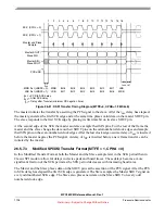
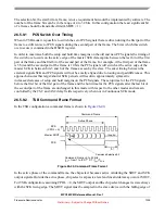
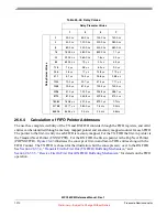
Figure 26-34. Example of Non-Continuous Format (CPHA=1, CONT=0)
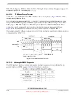
When the CONT bit = 1, the PCS signal remains asserted for the duration of the two transfers. The Delay
between Transfers (t
DT)
is not inserted between the transfers.
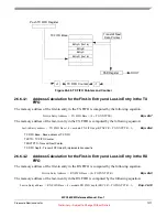
two four-bit transfers with CPHA = 1 and CONT = 1.
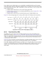
Figure 26-35. Example of Continuous Transfer (CPHA=1, CONT=1)
Switching CTAR registers or changing which PCS signals are asserted between frames while using
Continuous Selection can cause errors in the transfer. The PCS signal should be negated before CTAR is
switched or different PCS signals are selected.
t
CSC
t
DT
t
CSC
SCK
PCSx
SCK
Master SOUT
Master SIN
t
CSC
= PCS to SCK delay
t
DT
= Delay after Transfer (minimum CS negation time)
(CPOL = 0)
(CPOL = 1)
t
ASC
t
ASC
= After SCK delay
t
CSC
t
CSC
SCK
PCS
SCK
Master SOUT
Master SIN
t
CSC
= PCS to SCK delay
(CPOL = 0)
(CPOL = 1)
t
ASC
(CPOL = 0)
SCK
t
ASC
= After SCK delay


