


MPC563XM Reference Manual, Rev. 1
Freescale Semiconductor
1107
Preliminary—Subject to Change Without Notice
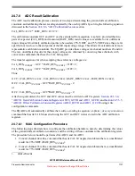
24.7.6
ADC Result Calibration
The ADC result calibration process consists of two steps: determining the gain and offset calibration
constants, and calibrating the raw results generated by the on-chip ADCs by solving the following equation
discussed in the
Section 24.6.6.6, “ADC Calibration Feature
section.
CAL_RES = GCC * R OCC+2;
The calibration constants GCC and OCC can be calculated from equation <st-plain> provided that two
pairs of expected (CAL_RES) and measured (RAW_RES) result values are available for two different
input voltages. Most likely calibration points to be used are 25% VREF
1
and 75% VREF since they are far
apart but not too close to the end points of the full input voltage range. This allows for calculations of more
representative calibration constants. The EQADC provides these voltages via channel numbers 43 and 44.
The raw, uncalibrated results for these input voltages are obtained by converting these channels with
conversion commands that have the CAL bit negated.
The transfer equations for when sampling these reference voltages are:
CAL_RES
75%VREF
= GCC * RAW_RES
75%VREF
+ OCC+2;
CAL_RES
25%VREF
= GCC * RAW_RES
25%VREF
+ OCC+2;
Thus;
GCC= (CAL_RES
75%VREF
- CAL_RES
25%VREF
) / (RAW_RES
75%VREF
- RAW_RES
25%VREF
);
OCC= CAL_RES
75%VREF
- GCC*RAW_RES
75%VREF
- 2;
or
OCC= CAL_RES
25%VREF
- GCC*RAW_RES
25%VREF
- 2;
After being calculated, the GCC and OCC values must be written to ADC registers:
“ADC0/1 Gain Calibration Constant Registers (ADC0_GCCR and ADC1_GCCR)
“ADC0/1 Offset Calibration Constant Registers (ADC0_OCCR and ADC1_OCCR)
configuration commands.
The EQADC will automatically calibrate the results, according to equation <st-plain>, of every conversion
command that has its CAL bit asserted using the GCC and OCC values stored in the ADC calibration
registers.
24.7.6.1
MAC Configuration Procedure
The following steps illustrate how to configure the calibration hardware, namely, determining the values
of the gain and offset calibration constants, and the writing of these constants to the calibration registers.
The procedure below should be performed for ADC0 and for ADC1.
1.
Convert channel 44 with a command that has its CAL bit negated and obtain the raw, uncalibrated
result for 25%VREF (RAW_RES
25%VREF
).
2.
Convert channel 43 with a command that has its CAL bit negated and obtain the raw, uncalibrated
result for 75%VREF (RAW_RES
75%VREF
).
1.
VREF=VRH-VRL


