


LIN Frames and Signals
LIN Leveller Configuration Frames
DRM047 — Rev 0
Designer Reference Manual
MOTOROLA
LIN Frames and Signals
101
distinguish the nodes when using
.
NOTE:
The default node ID settings of the LIN Stepper software reflect the
configured axis; so, Axis3 has node ID = 4, Axis2 has node ID = 3,
Axis1_2 has node ID = 2, Axis1_1 has node ID = 1. However, both the
configuration axis and the node ID can be independently changed in the
software or during configuration. The user must guarantee that there will
be no other nodes with the same node ID connected to one LIN-bus.
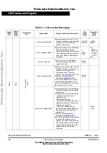
C.3 LIN Leveller Configuration Frames
The Master Request and Slave Response frames were used for the LIN
Stepper Controller configuration. The configuration allows, on LIN,
adaptation of the LIN Stepper software. Each configuration frame is
used to configure the LIN Stepper Controller with node ID equal to the
l_u8_rd_nodeID signal (see
).
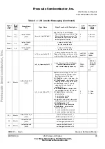
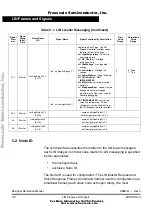
The configuration process covers two functions:
1. Parameters Configuration
Provides upload and download of the control parameters from and
to
paramRAM
structure. The paramArray variable with a
dedicated signal l_u8_rd_paramArray defines the section of the
parameters sent in four data signals l_u8_rd_datax. It is also
described in
service, the parameters updated in the configuration are stored in
paramRAM
volatile structure.
The service l_u8_rd_service = Store (FLASH) provides storing of
all RAM parameters arrays = paramRAM to paramROM. The
paramROM is in the FLASH memory and is copied to the
paramRAM after any MCU reset.
The service l_u8_rd_service = MCU Reset forces the reset of
dedicated LIN Stepper Controller
F
re
e
sc
a
le
S
e
m
ic
o
n
d
u
c
to
r,
I
Freescale Semiconductor, Inc.
For More Information On This Product,
Go to: www.freescale.com
n
c
.
..


