


Debug LEDs
Technical Summary, Rev. 0
Freescale Semiconductor
2-3
Preliminary
.
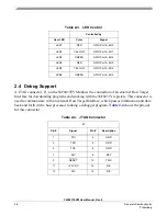
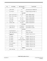
Table 2-2. SCI TxD Signal Options
JG4
Pin #
Signal
Description
1
GPIO Port B, Bit 7
TXD0
2
TxD
To CP2102
3
GPIO Port C, Bit 8
TXD1
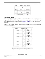
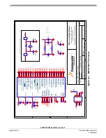
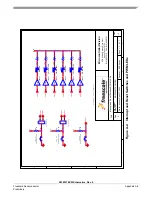
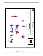
2.3 Debug LEDs
Six on-board Light-Emitting Diodes, (LEDs), are provided to allow real-time debugging for user
programs. These LEDs will allow the programmer to monitor program execution without having
to stop the program during debugging; refer to
Figure 2-1
.
Table 2-3
describes the control of
each LED.
Setting GPIOA0, GPIOA1, GPIOA2, GPIOA3, GPIOA4, or GPIOA5 to a Logic One value will
turn on the associated LED.
56F8037
INVERTING BUFFER
GPIOA0
GPIOA1
GPIOA2
GREEN LED
YELLOW LED
RED LED
+3.3V
GREEN LED
YELLOW LED
RED LED
GPIOA3
GPIOA4
GPIOA5
Figure 2-1. Diagram of the Debug LED Interface
Summary of Contents for 56F8037
Page 2: ......
Page 4: ...56F8037EVM User Manual Rev 0 ii Freescale Semiconductor Preliminary ...
Page 6: ...56F8037EVM User Manual Rev 0 iv Freescale Semiconductor Preliminary ...
Page 8: ...56F8037EVM User Manual Rev 0 vi Freescale Semiconductor Preliminary ...
Page 18: ...56F8037EVM User Manual Rev 0 1 6 Freescale Semiconductor Preliminary ...
Page 38: ...56F8037EVM User Manual Rev 0 Appendix B 4 Freescale Semiconductor Preliminary ...