background image

9

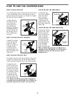
HOW TO USE THE PEDALS

To use the toe cage side of the pedals (see the draw-

ing on page 4), insert your shoes into the toe cages 

and pull the ends of the toe straps. To adjust the toe 

straps, press and hold the tabs on the buckles, adjust 

the toe straps to the desired position, and then release 

the tabs.

To use the clip-in side of the pedals, you must wear 

cycling shoes. To clip into the pedals, press the cleats 

on your cycling shoes firmly into the slots in the pedals 

until they snap into place. To unclip from the pedals, 

twist your cycling shoes outward from the pedals. 

HOW TO ADJUST THE PEDALING RESISTANCE 

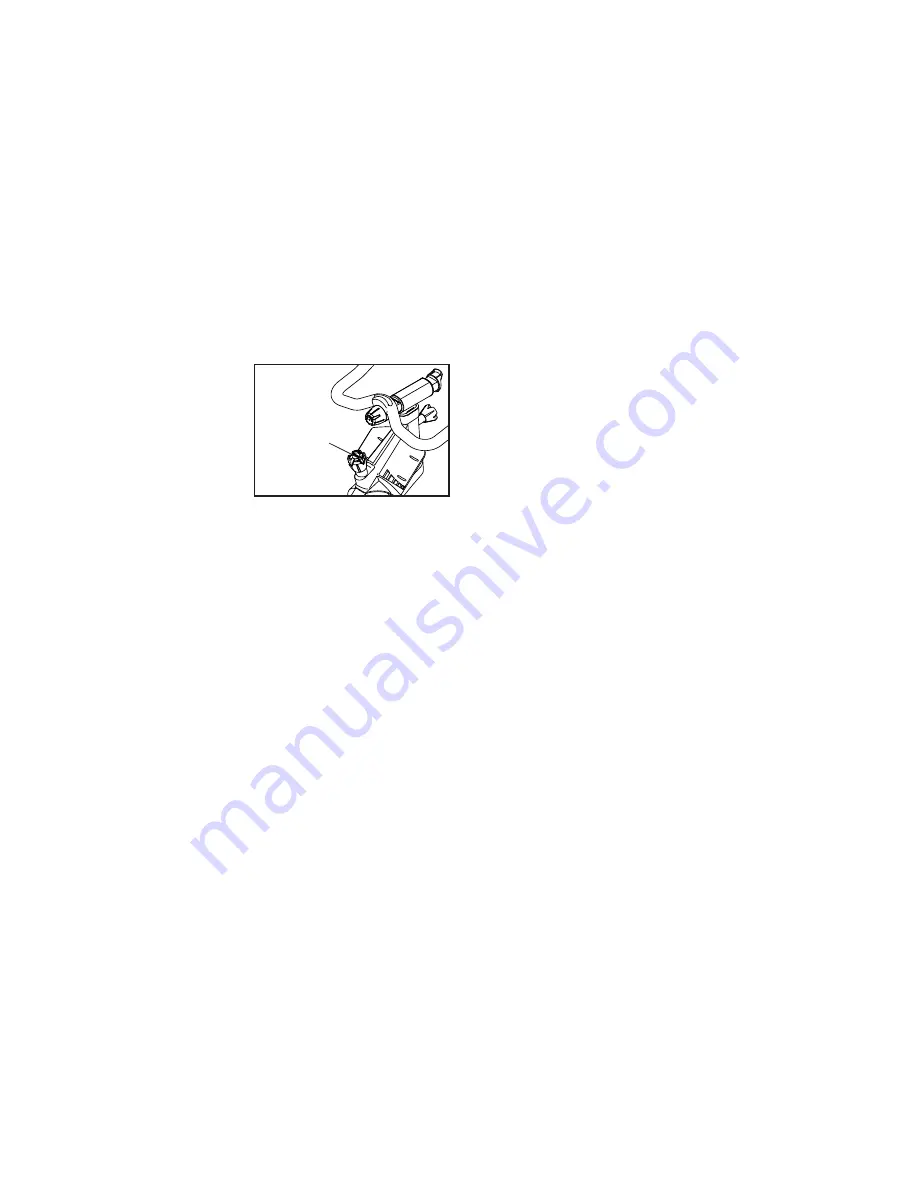
To increase the resis-

tance of the pedals, 

turn the resistance 

knob clockwise; 

to decrease the 

resistance, turn the 

resistance knob 

counterclockwise. 

To stop the flywheel, push the resistance knob 

downward. The flywheel should quickly come to a 

complete stop. 

IMPORTANT: When the exercise bike is not in use, 

tighten the resistance knob completely.

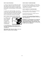
HOW TO LEVEL THE EXERCISE BIKE

If the exercise bike rocks slightly on your floor during 

use, turn one or both of the leveling feet on the front or 

rear stabilizer (see the drawing on page 4) until the 

rocking motion is eliminated.

HOW TO MAINTAIN THE EXERCISE BIKE

Inspect and tighten all parts of the exercise bike regu-

larly. Replace any worn parts immediately. 

To clean the exercise bike, use a damp cloth and a 

small amount of mild detergent.

For maximum performance and safety, replace the 

pedals every year. To purchase pedals, see the back 

cover of this manual. 

IMPORTANT: To avoid damage to the exercise bike 

and to prevent injury to the user, use only manu-

facturer-supplied pedals. Other pedals may not be 

designed for use in fitness clubs or indoor cycling 

studios and may be dangerous.

Resistance 

Knob

Summary of Contents for CARBON S11.8

Page 1: ...for reference CAUTION Read all precautions and instruc tions in this manual before using this equipment Keep this manual for future reference QUESTIONS If you have questions or if parts are damaged or...

Page 2: ...RNING DECAL PLACEMENT TABLE OF CONTENTS 310696 This drawing shows the location s of the warning decal s If a decal is miss ing or illegible see the back cover of this manual and request a free replace...

Page 3: ...eath it to protect the floor or carpet Make sure that there is at least 2 ft 0 6 m of clearance around the exercise bike 7 Inspect and properly tighten all parts regu larly Replace any worn parts imme...

Page 4: ...ise bike If you have questions after reading this manual please see the back cover of this manual To help us assist you note the product model number and serial number before contacting us The model n...

Page 5: ...ls Do not dispose of the packing materials until you complete all assembly steps If a part is not in the hardware kit check to see if it has been preassembled To avoid damaging parts do not use power...

Page 6: ...as shown Loosen the Post Knob 32 on the front of the Frame 1 and pull it outward Then insert the Handlebar Post 2 into the Frame Move the Handlebar Post 2 upward or down ward to the desired position...

Page 7: ...ilizers 7 8 until all four Leveling Feet contact the floor 29 7 8 29 29 6 Make sure that all parts are properly tightened before you use the exercise bike Note After assembly is completed some extra p...

Page 8: ...the seat post first loosen the post knob and pull it outward Then move the seat post upward or downward release the post knob into an adjustment hole in the seat post and firmly tighten the post knob...

Page 9: ...push the resistance knob downward The flywheel should quickly come to a complete stop IMPORTANT When the exercise bike is not in use tighten the resistance knob completely HOW TO LEVEL THE EXERCISE B...

Page 10: ...p 53 2 11mm x 20mm Washer 54 1 Block Pin 55 2 Small E clip 56 1 M3 x 6mm Flat Head Patch Screw 57 2 M5 Washer 58 2 M5 Star Washer 59 2 M5 x 10mm Button Screw 60 12 M4 x 8mm Button Patch Screw 61 1 M8...

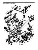
Page 11: ...83 19 79 20 21 22 64 32 33 37 37 35 35 33 36 63 38 38 68 39 69 69 39 39 40 60 41 42 42 71 71 45 43 70 70 70 43 44 44 34 39 36 46 46 60 60 60 60 47 47 6 76 76 77 77 88 86 28 29 29 28 29 29 15 85 87 87...

Page 12: ...f this manual before contacting Customer Care If you are ordering replacement parts please also note the key number and description of each part see the PART LIST and the EXPLODED DRAWING near the end...

Reviews: