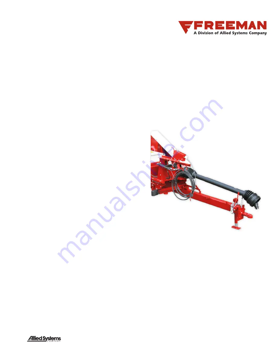
SIDE FEED BALER
540 RPM Driveline
Operator’s and Parts Addendum
A Product of
Sherwood, Oregon USA
89-052
Rev: 1/2020
Page 1: ...SIDE FEED BALER 540 RPM Driveline Operator s and Parts Addendum A Product of Sherwood Oregon USA 89 052 Rev 1 2020...
Page 2: ...r Installation PTO 16 Drawbar Assembly PTO 17 Driveline PTO Installation 19 Driveline Assembly 22 Clutch Assembly Driveline 23 Shielding Installation Drive Belt 24 Shield Installation Top Chamber 25 T...
Page 3: ...ic ipated so as to be included in this manual There fore you must always be alert to potential hazards that could endanger personnel and or damage the equipment Safety Symbols The following symbols te...
Page 4: ...specific directions and procedures The methods outlined in this manual provide a basis for safe operation of the baler Because of special conditions your company s baling procedures may be somewhat di...
Page 5: ...rgized equipment Do not rely on the hydraulic system to support any part of the baler during maintenance or lubrica tion Never stand under a baler component that is supported only by the hydraulic sys...
Page 6: ...l protective equipment PPE appropriate to the situation This may include the use of hearing protection eye protection a respi rator a hard hat leather gloves steel toed boots etc Electrical Hazards An...
Page 7: ...least a fire extinguisher at hand Hydraulic fluid is flammable Do not weld on or near pipes tubes or hoses that are filled with fluid Do not smoke when checking or filling the tank Keep open flames a...
Page 8: ...them as danger zones Always walk around the equipment to avoid being near the PTO Stepping over leaning across or crawling under a rotating PTO driveline no matter how slowly it may be turning can eas...
Page 9: ...od working order and rotate freely The shaft and tube of the telescopic shaft should be well lubricated so that the PTO shaft can telescope freely see Figure 4 Check oil level in the PTO gearbox befor...
Page 10: ...he ground speed will decrease the amount of material in the feeder house thus increasing the num ber of plunger strokes in each bale If enough material can not be kept in the feeder house by increasin...
Page 11: ...r annualy whichever comes first 1 Place a catch pan in the space beneath the gearbox under the drain plug 2 Remove the drain plug from the bottom of the gear box via the access hole in the gearbox mou...
Page 12: ...grease should be removed from inside the shields Never operate the driveline with out all of its shielding in place and in good condition Figure 5 Driveline Lubrication Points and quantities Lubricat...
Page 13: ...ould be 0 748 0 008 at each bolt Adjust each nut to maintain this measurement Avoid excessive tightening of the bolts implement tractor or driveline damage may occur Following seasonal use relieve the...
Page 14: ...ssemblies are the same A R as required identifies bulk items whose length or other dimension must be specified when requisi tioning Ref identifies items shown for reference purposes only to illustrate...
Page 15: ...pring 4 904098 1 Mounting RH 5 F000008247 2 Washer 6 904100 2 Plate Support 7 904099 1 Mounting LH 8 PLF0026952 1 Pickup Lift Lever 9 909778 1 Hitch Base 10 R13806345 3 Capscrew 11 234176 2 Capscrew 1...
Page 16: ...art No Qty Description 904110 Drawbar Installation PTO 1 JCK0178203 1 Jack 2 NSL0001000 1 Nut Castle 3 PIN0018909 1 Pin 4 ROP0000012 1 Rope 5 904111 1 Drawbar Assembly 6 212255 1 Cotter Pin See Separa...
Page 17: ...696 1 Bar Link 10 PLT0011228 1 Plate Tongue Latch 11 904112 1 LH Drawbar 12 221574W 4 Capscrew 13 221499W 1 Capscrew 14 Y17C 0624 1 Capscrew 15 R13801813 1 Capscrew 16 221560W 2 Capscrew 17 R13811077...
Page 18: ...t 24 R13801813 4 Capscrew 25 a 258050 1 Driveline 26 904434 1 Cover Weldment Shaft 27 b 904680 1 Clutch 1 Taper Pin 1 Washer 1 Nut 28 904562 1 Plate Guard 29 904490 1 Plate Mounting 30 R13811017 4 Cap...
Page 19: ...IGHTEN CONNECTION BOLT FROM DRIVELINE TO GEARBOX INPUT SHAFT TO 162 FT LBS ADJUST SCREW LENGTH SO SUPPORT BAR IS IN A VERTICAL POSITION WHEN DRIVELINE IS PLACED IN HOLDER ENGAGE JAM NUT TO LOCK SCREW...
Page 20: ...Driveline PTO Installation 3 Tie Bull Gear Page 3 of 5 2C1 DETAIL 2C1 GEARBOX MOUNTING PLATE 22 7 9 6 7 3 4 5 7 6 2X 4X 11 56 6 7 2X 10 7 1 9 4X 20 89 052 Rev 1 2020...
Page 21: ...80W 90 GEAR OIL ALLIED P N 235720 WITH THE BALER SITTING LEVEL REMOVE THE LOWER PLUG OIL SHOULD BE LEVEL WITH THE BOTTOM OF THE OPENING SEE VIEW GEARBOX FILLING AND DRAIN ADD OIL AS NECESSARY THROUGH...
Page 22: ...ge 5 of 5 SECTION 2D2 2D2 SECTION 2F2 2F2 2D2 2D2 2F2 2F2 14 15 38 43 44 43 44 48 VIEW 2E2 2E2 29 8 23 8 23 49 14 15 3X 23 50 DETAIL 2B1 INSTRUMENT PANEL 2E2 2E2 35 41 35 41 40 42 36 13 37 39 55 BRACK...
Page 23: ...te 13 906334 1 Shield Outer 1 2 Shaft 14 906289 1 CV Shield Cone Bearing Ring 15 906290 1 CV Shield Cone 16 906291 1 Bearing Ring Outer Tube 17 906329 1 Shield Outer Tube 18 906293 1 Outer Safety Deca...
Page 24: ...g 8 4 906265 1 Drive Plate 5 906266 1 Inner Plate 6 906267 1 Seal Plate 7 906268 1 Housing w Flange 8 252028 1 Grease Fitting 9 906269 1 Pressure Plate 10 906270 1 Belleville Spring 11 906271 1 Retain...
Page 25: ...lation Belt Driveline Balers 1 904145 1 Shield Sub Assembly Belt 3 399741W 1 Screw Ser Flg 4 221763W 1 Washer 6 2305631W 2 Screw Ser Flg See Separate Coverage Rev A SHOWN WITHOUT SHIELD 1 6 USE EXISTI...
Page 26: ...Top Chamber Bullgear Hydro and Driveline Balers 1 SHD037519D 1 Plate Top Shield 3 162572W 1 Capscrew 4 221767W 1 Washer 5 R13812514 1 Lockwasher 7 R13801791 1 Capscrew 8 R13811015 2 Capscrew 9 R13812...
Page 27: ...evis 8 BKT0024669 1 Bracket Rear 9 R13811014 2 Capscrew 10 Y17C 0616 6 Capscrew 11 SMS0000300 2 Bolt Whiz 12 223428 6 Flat Washer 13 09416918 2 Nut Serrated 14 00273802 2 Nut Serrated 15 237567 6 Nut...
Page 28: ...VIEW B B CABLE INSIDE TENSION CONTROL LEFT SIDE VIEW C C TENSION CONTROL BOX MOUNT RIGHT SIDE DETAIL D 11 13 8 4 18 2X 18 4 7 7 10 15 1 14 19 9 2X 6X 6X 2X 3 2 9 12 12 12 14 5 3 9 12 12 12 14 5 6 Pag...
Page 29: ...F000001005 1 Adjusting Stud Nut 5 F000001006 1 Rod 6 905968 2 Washer Brass 7 MNT0024671 1 Plate Control Box 8 NCA0003125 1 Nut Acorn 9 00273802 5 Nut Serrated 10 SMS0000184 2 Screw Ser Flg 11 18515W 8...
Page 30: ...3 1 2 1 v e R 2 f o 1 e g a P A 9 0 6 0 9 5 LIGHT INSTALLATION 70 75 DRIVELINE A B C D E F G Light Installation 70 75 Driveline 30 89 052...
Page 31: ...1 25 NOTES ALL CLAMP LOCATIONS ARE NOT SHOWN USE CLAMP P N 209579 AND SCREW R13810989 AS NEEDED TO SECURE WIRE HARNESS P N 906097 1 DETAIL A DETAIL B BACKSIDE OF DETAIL A 13 3X 8 REFERENCE TENSION CON...
Page 32: ...ORG 16 1 4 M 1 4 F ORG 16 WHT 16 FAN SWITCH NOT SHOWN IN INTALLED POSITION 1 4 F OPTIONAL NOTES WIRE HARNESS ONLY REQUIRED IF KNOTTER FAN OPTION IS INSTALLED SWITCH INSTALLED ON KNOTTER FAN ASSEMBLY...
Page 33: ...CH YEL 16 WHT 16 WHT 16 PUR 14 WHT 16 901521 REAR WORK LIGHT WHT 16 A BC D D C B A BRN 16 RED 16 RED 16 BRN 16 GRY 12 WHT 12 GRY 12 GROUND PIN A RIGHT TURN PIN B 12V PIN C LEFT TURN PIN D TAIL LIGHTS...
Page 34: ...RN 16 RED 16 YEL 16 RED 16 YEL 16 BRN 16 GRN 16 PUR 14 WHT 12 BLU 12 PUR 14 WHT 12 PUR 14 WHT 16 WHT 16 PUR 14 YEL 16 WHT 16 WHT 16 PUR 14 WHT 16 WHT 16 D C B A BRN 16 RED 16 RED 16 BRN 16 B A PUR 14...
Page 35: ...This page is intentionally left blank 35 89 052 Rev 1 2020...
Page 36: ...To find a dealer in your area Call 503 625 2560 Fax 503 625 7269 or Visit our website http www alliedsystems com 89 052 12 2013 Printed in USA...