TPA400 Rev0509
1
FIRE RESEARCH CORPORATION
www.fireresearch.com
26 Southern Blvd., Nesconset, NY11767
TEL ( 631 ) 724-8888 FAX ( 631 ) 360-9727 TOLL FREE 1-800-645-0074
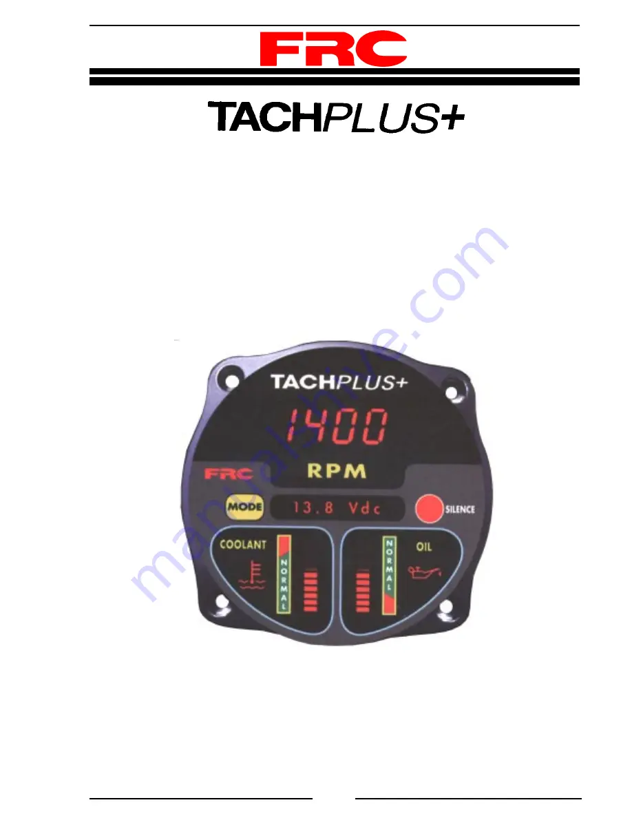
ENGINE DISPLAY AND MONITORING SYSTEM
MODELS: TPA400, TPA420, TPA450
Document Number:
XE-TPA4PM-R0A


