


PRO-S Rev1104
32
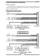
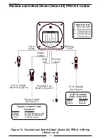
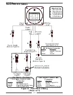
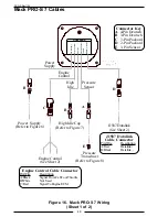
Non-Electronic Engine PRO-S 3 Cables
Figure 12. Non-Electronic PRO-S 3 Wiring
(Sheet 1 of 2)
Power
Supply
Engine
Control
-Power Supply
-Engine Control
-High Idle
-Pressure Sensor
-Throttle
-RPM Sig./ J1587
GOVERNOR
High
Idle
Pressure
Sensor
RPM Sig.
/ J1587
A
B
B
Power Supply
(Refer to Figure 6)
E
C
D
Throttle Servo
Motor
(Refer to Figure 5)
Alternator
(See Sheet 2)
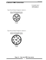
Connector Key
A 4-Pin Deutsch
B 3-Pin Deutsch
C 2-Pin Deutsch
D 2-Pin Packard
E 3-Pin Sensor
Alternator Cable
Connector
Pin/Wire
Description
1/Red
+ Terminal
2/Black
Ground
High Idle Cap
(Refer to Figure 7)
Pressure
Transducer
(Refer to Figure 8)
Note: Extend refers to the
INCREASE direction as shown
on the servo motor.
Throttle Servo Motor Cable
Connectors
Pin/Wire
Description
A/Red
+12 VDC to Extend
B/Black
+12 VDC to Retract