background image

DGA200 Rev160525

1

FIRE RESEARCH CORPORATION

www.fireresearch.com

26 Southern Blvd., Nesconset, NY 11767

TEL  631.724.8888   FAX  631.360.9727   TOLL FREE  1.800.645.0074

Document Number:

XM-DGA2PM-R0A

DRYING SYSTEM

ASSEMBLY AND OPERATING MANUAL

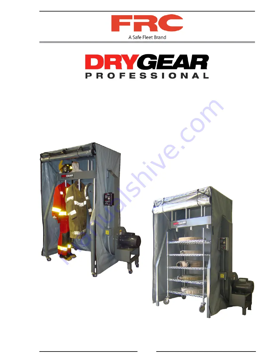
DRY GEAR PLUS

w/Removable Hangers

DRY GEAR PRO

Summary of Contents for DRY GEAR PLUS

Page 1: ...ION www fireresearch com 26 Southern Blvd Nesconset NY 11767 TEL 631 724 8888 FAX 631 360 9727 TOLL FREE 1 800 645 0074 Document Number XM DGA2PM R0A DRYING SYSTEM ASSEMBLY AND OPERATING MANUAL DRY GE...

Page 2: ...re 9 Tent Enclosure 23 Figure 10 Caster Kit 25 Figure 11 Wiring Power 27 Figure 12 Control Box Panel 29 Table of Contents CONTENTS 2 INTRODUCTION 3 Overview 3 Specifications 4 ASSEMBLY INSTRUCTIONS 5...

Page 3: ...tor heater element thermistor and control box It supplies warm air to the manifold through the transfer tube The air intake for the blower is located inside the tent enclosure to increase the circulat...

Page 4: ...5 Volts 220 Amps 19 6 Heater Power 2400 Watts Current Maximum 10 AMPS Thermistor 180 F cutoff Timer 6 Hours Dimensions Length 3 station configuration 71 inches 4 station configuration 86 inches 6 stat...

Page 5: ...are Description 3 Station 4 Station 6 Station 7 Station 8 Station Screw Flat Head Socket Cap S S 1 4 20 x 1 2 12 12 24 24 24 Screw Socket Cap S S 1 4 20 x 3 4 28 28 44 44 44 Screw Socket Cap S S 1 4 2...

Page 6: ...Assembly Mount 1 1 1 1 1 1 Muffler 1 1 1 1 1 1 Leg Assembly 4 4 4 4 4 5th Leg Assembly 1 1 1 1 1 1 Leg Brace Blower Side 1 1 1 1 1 Leg Brace Non Blower Side 1 1 1 1 1 Transfer Tube 1 1 1 1 1 Manifold...

Page 7: ...t size tent frame long angles 50 and 65 inches put together with joining plates For the 8 station DryGear system two manifolds and two tent frame long angles 65 inches are put together with joining pl...

Page 8: ...2 Lock Washer 3 8 inch 2 Nut 3 8 16 Procedure 1 Install transfer tube 1 on blower assembly 3 with four screws 2 and washers 2 Install control box 6 on chimney assembly 1 with four screws 2 and washers...

Page 9: ...DGA200 Rev160525 9 Figure 2 Blower Assembly and Transfer Tube 5 1 3 4 6 Motor Slotted Hole Slotted Hole 2 2...

Page 10: ...ead Socket Cap Screw 1 4 20 1 2 inch 4 16 Socket Cap Screw 1 4 20 3 4 inch 2 16 Flat Washer 1 4 inch Procedure NOTE The distance from the end of the manifold to the manifold glove mount holes is diffe...

Page 11: ...nd Tent Frame Long Angles 6 Station Manifold 8 Station Manifold 7 Station Manifold 1 3 1 2 4 1 4 4 1 4 5 5 4 6 NOTE The distance between the glove post holes and the correct end of the manifold at the...

Page 12: ...8 Nut 1 4 20 26 Flat Washer 1 4 inch Procedure NOTE The blower side leg brace 6 has two holes for attaching the blower assembly Ensure that these holes are on the blower side as shown in figure 4 1 Co...

Page 13: ...DGA200 Rev160525 13 Figure 4 Leg Assemblies 3 7 Non Blower Side 1 4 5 8 2 Blower Side 1 Holes 6...

Page 14: ...2 4 Flat Washer 3 8 inch 2 Nut 3 8 16 Procedure NOTE The side lower screws that hold the blower side legs to transfer tube do not have washers 1 Connect blower side legs to transfer tube with eight s...

Page 15: ...DGA200 Rev160525 15 Figure 5 Blower Assembly Legs Blower Side Legs Transfer Tube 3 Blower Assembly Mount Leg Brace 1 Blower Assembly 2 4...

Page 16: ...a joining plate Refer toAssemble Manifold and Tent Frame Long Angles instructions 2 Tent Frame Long Angle 2 2 Tent Frame End Support 3 12 Flat Head Socket Cap Screw 1 4 20 1 2 inch 4 Procedure NOTE F...

Page 17: ...DGA200 Rev160525 17 Figure 6 Tent Frame 1 2 3 4...

Page 18: ...inches 1 4 Socket Cap Screw 1 4 20 3 4 inches 2 14 Flat Washer 1 4 inch Procedure 1 Install manifold in transfer tube top with six screws 1 and washers NOTE For 7 station configuration mount the 60 in...

Page 19: ...DGA200 Rev160525 19 Figure 7 Manifold Tent Frame and Muffler Manifold 4 Station Manifold Shown Tent Frame 3 View Rotated 90 for Clarity Blower Assembly 2 1 Transfer Tube Blower Assembly...

Page 20: ...k Washer 5 16 inch Procedure NOTE Make sure the hanger manifold air opening is towards the blower assembly end of the manifold 1 Slide hanger 3 into hole in bottom of manifold with hanger manifold air...

Page 21: ...igure 8 Hanger and Glove Post Typical Installation Manifold Hanger Manifold Air Opening 1 3 2 NOTE Make sure the hanger manifold air opening is towards the blower assembly The removable hanger install...

Page 22: ...TE There are two different length cords provided The shorter cord attaches to the inner D ring closest to the Velcro strap 4 Connect cord clips to inner D rings 5 Drop cord ends down under tube and up...

Page 23: ...gurations is a mirror image NOTE Ensure that the tent frame long angle supports the nylon web between the D rings NOTE Loop the nylon web around the rear tent frame long angle and secure with Velcro O...

Page 24: ...ers two casters have a break mechanism Procedure NOTE The caster threaded leg plugs may be installed in the leg assemblies at the factory 1 Remove plastic leg plugs from leg assemblies 2 Install threa...

Page 25: ...DGA200 Rev160525 25 Figure 10 Caster Kit Leg Assembly Caster Threaded Leg Plug...

Page 26: ...res will support the panel Do not remove wiring to the controls NOTE There are two 3 4 inch access holes in the control box The power cable is installed through either the top or bottom hole 2 Install...

Page 27: ...Amp Service To Blower Assembly Control Box Input Power Terminal Block Control Box internal wiring not shown for clarity Power Cable Top Access Hole Power Cable Bottom Access Hole Control Box Customer...

Page 28: ...may be placed inside the enclosure Remove the hanger assemblies DryGear Plus only to roll in racks of hose or loose equipment 1 Place SELECT switch to AIR ONLY position NOTE If the timer is to be set...

Page 29: ...Figure 12 Control Box Panel NOTE For less than one hour of operation rotate BLOWER HEATER HOURS switch past 1 then back to desired time BLOWER HEATER HOURS TIMER SWITCH Control Box HEATER SELECTED Ind...

Page 30: ...DGA200 Rev160525 30 NOTES...

Page 31: ...DGA200 Rev160525 31 NOTES...

Page 32: ...DGA200 Rev160525 32...

Reviews: