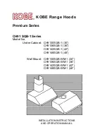
A. Igniter electrode
B. Burner base
C. Burner head
D. Burner cap
E. Spud
A. Stamped number
XXX
A
A
A
E
D
C
B
A
D
C
B
A
LP Gas Orifice Spud Chart for Standard
Surface Burners
To Convert Standard Surface Burners
1.
Remove burner cap.
2.
Apply masking tape to the end of a 7 mm
nut driver to help hold the gas orifice spud in
the nut driver while changing it. Press nut driver
down onto the gas orifice spud and remove by
turning it counterclockwise and lifting out.
Set gas orifice spud aside.
3.
Gas orifice spuds are stamped with a number,
on the side. Replace the Natural gas orifice
spud with the correct LP gas orifice spud.
Refer to the following chart for correct LP gas
orifice spud placement.
4.
Place Natural gas orifice spuds in plastic
parts bag for future use and keep with
literature package.
5.
Replace burner cap.
6.
Repeat steps 1-6 for the remaining burners.
7.
Adjust the minimum flow.
The flame can ben adjusted using the
adjustment screw (A) in the center of the
valve stem.
The valve stem is located directly underneath
the control knob.
Attention:
on taps with a security valve, the
minimum adjusting screw (A) is on the body
the control knob.
a)
Remove the control knob.
b)
Hold the knob stem with a pair of pliers.
Use a small flat-blade screwdriver to turn
the screw located in the center of the control
knob stem. The adjusting screw must be
tight screwed.
c)
Replace the control knob.
d)
Test the flame by turning the control from
LO to HI, checking the flame at each
setting.
IMPORTANT:
You may have to adjust the
LO setting for each cooktop burner.
29
Operating Instructions
Care and Cleaning
Troubleshooting
Tip
s
Safety Instructions
Inst
allation Instructions
Table D
MIN.
Btu/hr
Burners - head
Semi-rapid
Ø
2 / " (75mm)
Rapid
Ø
3 / " (100mm)
Wok
Ø
5 / " (131mm)
Auxiliary
Ø
2 / " (55mm)
No.
No.
Main Injector By-Pass *
73
93
100
53
31
42
65
27
Btu/hr
MAX.
6,000
10,000
11,000
3,500
1,600
2,500
5,000
1,000
64
64
61
16
15
128
21
WARNING: the range can have a
different burners disposition on the
work-top. To identify the burners on
the work-top, see table D, where
there are the diameters of their head.
All manuals and user guides at all-guides.com