3 INSTALLATION AND PREPARATION
3.1 Ambient temperature
Maximum: +40
º
C.
Should the temperature of the pumped liquid exceed
40
º
C, or in case of use at high altitude (higher than
1000 meters), the motor power reduces due to the
reduced density of air useful to cool the same. In some
cases, it may be necessary to replace the motor with
one with greater power.
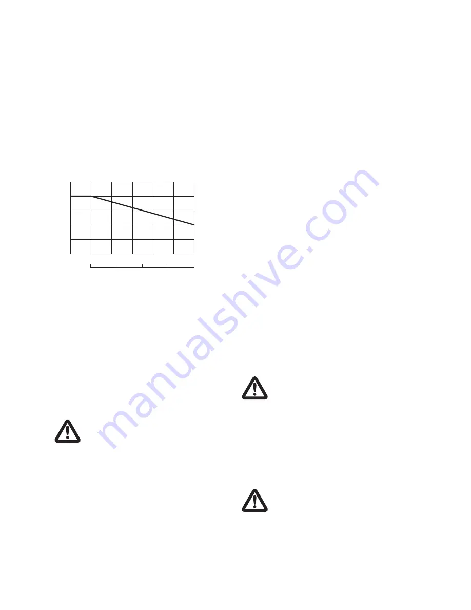
Here below there is an aproximate diagram
concerning the yield of the motors according to altitude
or temperature.
3.2 Minimum suction pressure
Check the characteristic curves of the pumps to assess
the NPSH factor and avoid cavitation problems (fig. 1
case B).
3.3 Maximum pressure during suction
It is important to keep the sum of the inlet and of the
outlet pressure, this latter against closed valve, always
lower than the maximum operation pressure allowed by
the pump (fig. 1 case A).
3.4 Minimum rate flow
The operation of the pump at a lower level than
the minimum rate flow allowed can cause excessive
overheating and damage the pump.
The pump must never operate against a
closed delivery valve.
3.5 Power supply data
See motor nameplate.
4 INSTALLATION
Legend figure 1:
1- Filter
2- Bottom valve
3- Gate valve
4- Pressure gauge
5- Check valve
6- Floating device
7- Anchorings for pipings
500
1000
1500
2000
2500
3000
3500
60
70
80
90
100
110
40
45
50
55
60
T °C
ambient
max
H m
altitude
max
P/Pn %
There can be two relevant application cases:
- Case shown in fig. 1.A: Pump under pressure, which
both from a tank as shown in figure and from civil
waterworks system, shall allow the plant to foresee a
protection against water lack (see fig. 1.6).
- Case shown in fig. 1.B: Pump in suction.
4.1 Assembly
Install the pump in an accessible place, protected
against frost and as close as possible to the water
suction point.
The pump must be tightly fastened to the basement by
means of bolts, for the measures of the holes and their
distance between centres, see the table on page 5.
To minimize the noise generated during the operation, it
is suggested to assemble the anti-vibration joints on the
tie rods fastening the base to the flooring.
Before proceeding to the final tightening of the pump,
make sure that it is in vertical position, otherwise adjust
the position with proper shims.
On the base of the pump it is indicated, by means of
arrows, the inlet and output direction of the pumped
fluid. On the lantern there are the arrows indicating the
motor rotation direction.
The pump can be assembled vertically or horizontally,
in any case it must not be placed vertically with motor
located in the lower part.
To avoid unnecessary stresses on the pump body,
place some support brackets (see fig. 1.7) in order to
support the incoming and outcoming pipe.
To avoid air blows affecting the pump operation, foresee
an inclination of the incoming pipes not lower than 2%.
Protect the pump against possible water hammers
by means of a check valve (bottom valve). Install a
shut-off valve upstream and downstream of the pump
in order to allow its insulation in case of maintenance
and disassembly.
4.2 Electric connections
The electric connection must be carried out
by qualified technicians in compliance with
the regulation in force in the countries of
installation of the pump.
Before replacing the cover of the terminal board and
removing / disassembling the pump, make sure power
supply has been disconnected.
The data concerning motor power supply are given on
the rating plate of the same. Before starting the motor,
check that electric power supply complies with the
features of the same.
For the connections, use electric cables complying with
local regulations.
When observed from above, standard 3VR,
5VR and 9VR pumps should rotate clockwise,
16VR should rotate counter-clockwise.
If necessary, the motor can be rotated on its axis to ease
the access to the same by maintenance technicians.
In this case, it is necessary to unscrew the screws
tightening the motor on the pump, remove the joint
covering safety carter and rotate the motor on its seat
paying attention not to remove the coupling joint.
2


