ELECTRICAL INSTALLATION
Power Wiring Connections
39
Power Wiring Connections
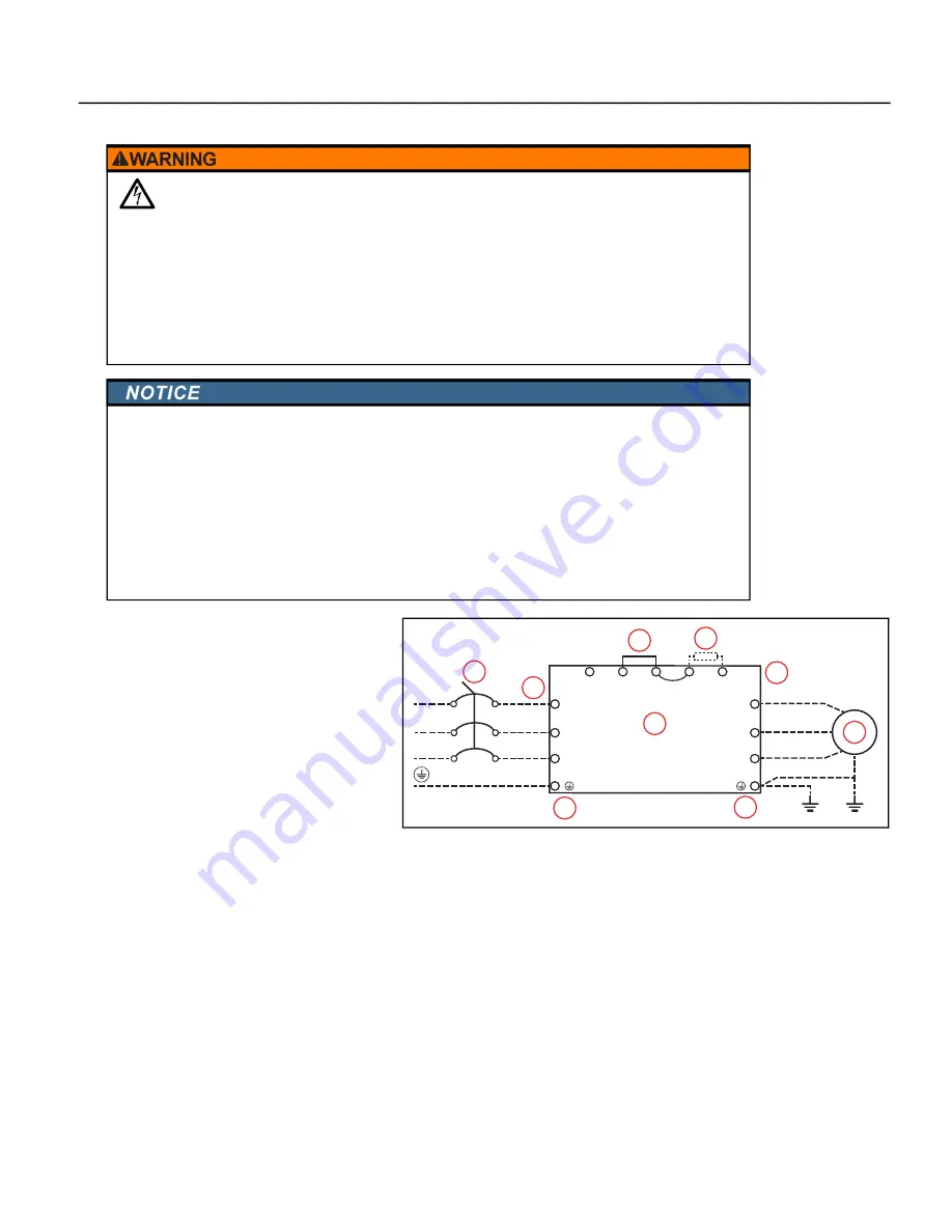
Power Wiring Diagram
1.
Branch Protection, Power
2. VFD
3. Motor
4. Ground Terminals
5. Power input terminals
6. Output to Motor terminals
7. Jumper (optional DC reactor, dynamic
brake or DC choke unit)
8. Optional brake resistor terminals
Use ring type terminals for the VFD power wiring.
Power line ground and motor ground wires should be connected to designated ground terminals.
Three-phase power, including Open-Delta, must be connected to the R(L1), S(L2), and T(L3) terminals.
Proper phase sequencing is not required.
•
For single-phase power, connect L1 to R and L2 to S terminals.
•
A, B, C, and D frame VFDs have single pole connections.
•
E and F frame VFDs have double-pole power terminals or lugs to accommodate two smaller gauge
wires.
•
G frame VFDs have four-pole connections on the input and double-pole connections on the out
-
put.
•
H frame VFDs have four-pole power terminals.
Connect three-phase motor wires to the U(T1), V(T2), and W(T3) terminals. When in forward rotation, the
motor shaft should turn clockwise when viewed from the motor to the load. If rotation is not correct, reverse
any two motor leads.
Contact with hazardous voltage could result in death or serious injury.
•
Disconnect and lock out all power before installing or servicing equipment.
•
Always check if DC bus charge LED is off and DC voltage on the terminals DC (+1) and DC (-) is less
than 30VDC before working on VFD wiring. The DC bus capacitors may hold high-voltage charge for
several minutes after the VFD power is disconnected.
•
Connect the motor, the drive, metal plumbing, and all other metal near the motor or cable to the
power supply ground terminal using wire no smaller than motor cable wires.
•
All wiring must comply with the National Electrical Code and local codes.
Risk of damage to VFD
,
or malfunction can occur.
•
Do not connect input power to VFD output terminals U, V, and W otherwise VFD can be damaged.
•
Ensure that the system is properly grounded all the way to the service entrance panel. Improper
grounding may result in loss of voltage surge protection and interference filtering.
•
Do not connect any wires except dynamic braking resistor to (B1) and (B2) terminals.
•
Do not remove the jumper between terminals (2+) and (1+) except for dynamic braking unit or DC
link choke, otherwise the VFD can be damaged.
•
When using a general GFCI (Ground Fault Circuit Interrupter), select a current sensor with sensitivity
of 200mA or above and not less than 0.1-second operation time to avoid nuisance tripping.
+2
(DC+)
R
–
(DC–)
+1
B1
B2
L1
L2
L3
S
T
U
V
W
T1
T2
T3
2
1
3
6
5
7
8
4
4
Summary of Contents for CERUS X-DRIVE CXD-003A-4V
Page 2: ......
Page 3: ...CERUS X DRIVE INSTALLATION AND OPERATION MANUAL Firmware Version 1 2 Franklin Electric Co Inc ...
Page 96: ...OPERATION Protection Features 96 ...
Page 112: ...ADVANCED APPLICATION OPTIONS Multi Drive Configurations 112 ...
Page 124: ...COMMUNICATIONS BACnet Communication 124 ...
Page 128: ...ACCESSORIES Optional Extension Cards 128 Frame D Frame E Frame F ...
Page 129: ...ACCESSORIES Optional Extension Cards 129 Frame G Frame H ...
Page 132: ...ACCESSORIES Optional Extension Cards 132 ...
Page 234: ...PARAMETER REFERENCE TABLES Parameter Descriptions Motor Menu 234 ...
Page 250: ...GLOSSARY 250 ...


