PHYSICAL INSTALLATION
Mounting the Drive
21
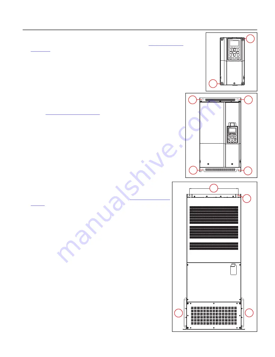
Mounting Frames A, B, and C
These frames have four corner mounting holes on the drive. Refer to
for mounting hole locations and sizes.
1.
Have one person hold the drive in location while another installs the lag screws in
each corner, ensuring they go into a solid stud or brace. Install the lower left lag
screw first.
2. Place a level on top of the drive. When level, install the upper right corner lag screw.
3. Install the remaining two lag screws.
Mounting Frames D0, D, and E
These frames have four corner mounting holes on the drive. The bottom two holes
are U-shaped slots, allowing the drive to be lowered onto pre-installed lag screws.
Refer to
for mounting hole locations and sizes.
1.
Install two lag screws for the bottom locations, ensuring they are level and enter
a solid stud or brace.
2. Use a lifting device to lower the U-shaped mounting slots onto the bottom lag
screws. The conduit box is not shown in this image to better show the bottom
mounting slots.
3. Hold the drive tight against the backing board, and install the remaining two lag
screws in the top mounting holes.
Mounting Frames F, G, and H
These frames include two keyhole shaped mounting holes at the top, allowing
the drive to be set onto pre-installed lag screws. Refer to
for mounting hole locations and sizes.
1.
Install two lag screws for the top locations, ensuring they are level and enter
a solid stud or brace.
2. Use a properly sized lifting device to lower the top keyhole shaped mount
-
ing slots onto the lag screws.
3. Hold the drive tight against the backing board, and install the remaining lag
screws in the bottom mounting holes, ensuring they enter a solid stud or
brace.
1
2
3
3
2
1
1
2
3
3
Summary of Contents for CERUS X-DRIVE CXD-003A-4V
Page 2: ......
Page 3: ...CERUS X DRIVE INSTALLATION AND OPERATION MANUAL Firmware Version 1 2 Franklin Electric Co Inc ...
Page 96: ...OPERATION Protection Features 96 ...
Page 112: ...ADVANCED APPLICATION OPTIONS Multi Drive Configurations 112 ...
Page 124: ...COMMUNICATIONS BACnet Communication 124 ...
Page 128: ...ACCESSORIES Optional Extension Cards 128 Frame D Frame E Frame F ...
Page 129: ...ACCESSORIES Optional Extension Cards 129 Frame G Frame H ...
Page 132: ...ACCESSORIES Optional Extension Cards 132 ...
Page 234: ...PARAMETER REFERENCE TABLES Parameter Descriptions Motor Menu 234 ...
Page 250: ...GLOSSARY 250 ...


