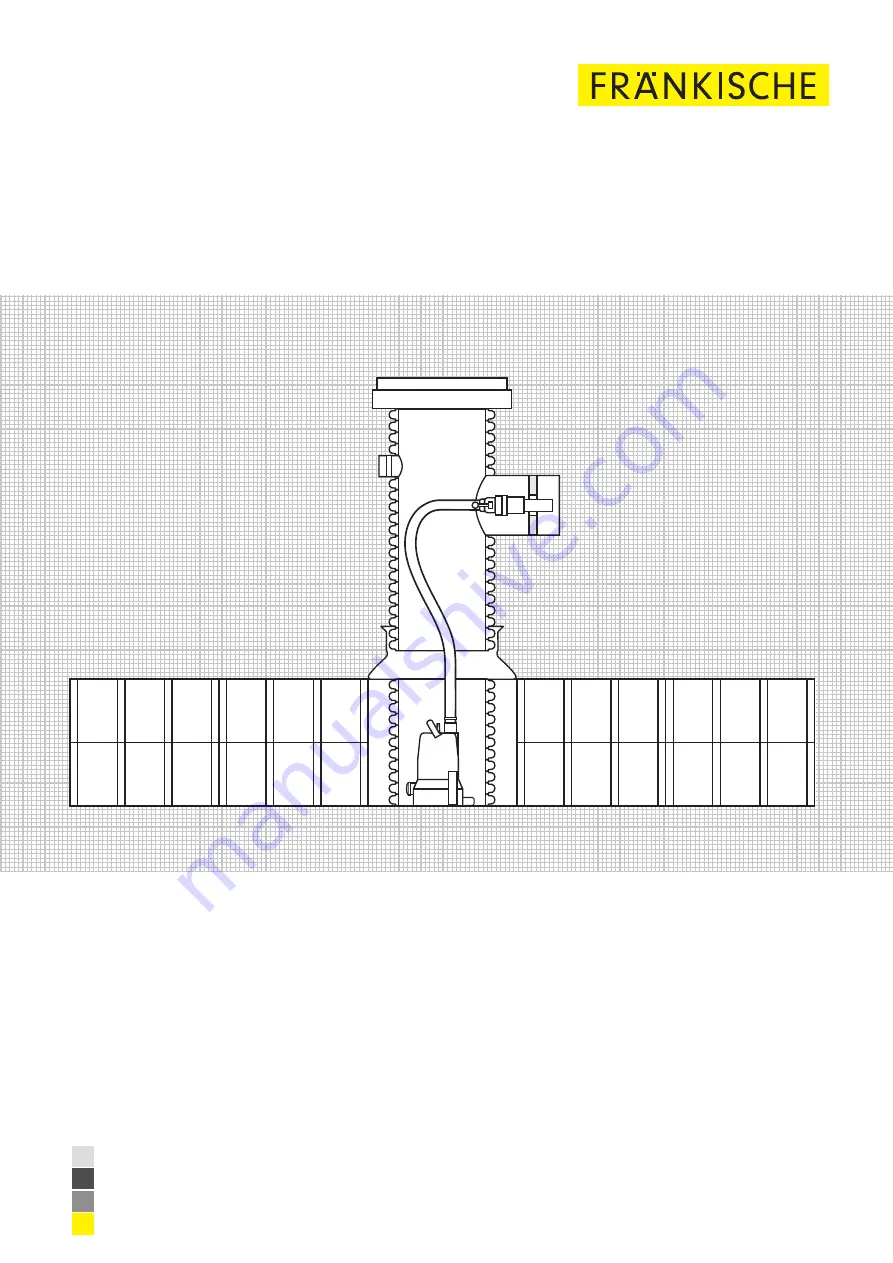
Quadro®Lift –
pump shaft
The pump shaft in the Rigofill modular block type structure
Installation manual
Drainage Systems
www.fraenkische.com
Page 1: ...Quadro Lift pump shaft The pump shaft in the Rigofill modular block type structure Installation manual Drainage Systems www fraenkische com...
Page 2: ...ct Contact persons K nigsberg headquarters International Sales Director European Sales Director European Sales International Sales Technology Julia M ller 49 9525 88 2394 julia moeller fraenkische de...
Page 3: ...ump sump 8 4 2 Placement of extension pipe with connection openings 10 4 3 Backfilling compacting up to the connection openings 13 4 4 Installing connecting the pressure line 13 4 5 Installing the con...
Page 4: ...esign QuadroLift is a versatile and modular pump shaft DO 600 You can integrate the sys tem pump shaft into the Rigofill system Maintenance does not require entering the shaft the pump unit can be eas...
Page 5: ...he installation of Rigofill storage infiltration modules www fraenkische de Rigofill inspect storage infiltration module QuadroControl flushing and inspection shaft Protective geotextile inside Protec...
Page 6: ...hey are protected from getting dirty Store the components on sleepers on plain ground Check the components for defects before installation The impact strength of the material decreases in sub zero tem...
Page 7: ...to it Use suitable lifting equipment to place the shaft in the intended position in the layout 2 Observe the correct orientation of the shaft openings The openings must always be orientated towards th...
Page 8: ...rane for the pump sump ATTENTION Install QuadroLift with its openings facing the direction of the tunnel QuadroLift with pump sump should be placed as the first component Carry out the remaining insta...
Page 9: ...been finished after the final layer has been installed Note Please observe the respective installation manual for the installation of Rigofill storage infiltration modules Install accessories Continue...
Page 10: ...er 4 2 2 Cutting the extension pipe without extension Top edge of terrain Temporary construction site cover To cut the extension pipe to length measure the height from the top temporary construction s...
Page 11: ...the extension pipe with extension to length measure the height from the top temporary construction site cover downwards NB You must always cut the pipe in the corrugation trough Height of extension p...
Page 12: ...cant to the sealing rings and the inside of the couple cone coupling do not use oils and greases 1 The extension pipes are inserted into the cone coupling coupling by means of sealing rings included i...
Page 13: ...ATTENTION We recommend having the system approved by site management before backfilling Do not remove included protective covers from shafts during backfilling n Backfill the excavation pit according...
Page 14: ...alling the fixture for the chain CAUTION Compacting by means of vibratory rollers and explosion rammers is not permissible ATTENTION Do not remove included protective covers from shafts during backfil...
Page 15: ...4034 under the shaft cover on an appropriate bearing The shaft cover can be placed on a 10 mm thick mortar joint to avoid stationary loads between equalisation ring and shaft cover Create the bearing...
Page 16: ...can connect the pressure line to the pump you must calculate the required length Use the following formula to calculate the length of the pressure line The calculated length must be measured from the...
Page 17: ...he chain to the lifting tool at the pump 1 Dismantle the screw terminal and the air valve at the end of the sensor cable 2 Push the cable gland and sensor bracket onto the cable 5 1 3 Connecting the p...
Page 18: ...Inserting the sensor into the base ATTENTION Make sure that the sensor does not protrude from the bottom of the fixture Now insert the sensor and the sensor bracket into the designated fixture at the...
Page 19: ...In addition make sure that the level sensor does not slip out of the fixture while lowering CAUTION Carefully lower the pump unit into the shaft The weight should be borne solely by the chain You must...
Page 20: ...installed connection Finally hook the chain into the upper section of the shaft 2 To fit the feed through watertight into the shaft opening hand tighten the four screws clockwise until the feed throu...
Page 21: ...allation manual QuadroLift 21 5 3 Installing the control cabinet NB Please observe the separate operating instructions for commissioning and handling the control unit These are enclosed with the deliv...
Page 22: ...Installation manual QuadroLift 22 Notes...
Page 23: ...eration maintenance and repair must have appropriate qualifications required for this kind of work The builder is responsible for organising in detail authority responsibility and supervision of staff...
Page 24: ...ge without notice Cat no 5000 1810 00 05 2022 DE 90139 1 FR NKISCHE Rohrwerke Gebr Kirchner GmbH Co KG Hellinger Str 1 97486 K nigsberg Germany Phone 49 9525 88 2200 Fax 49 9525 88 92200 marketing fra...