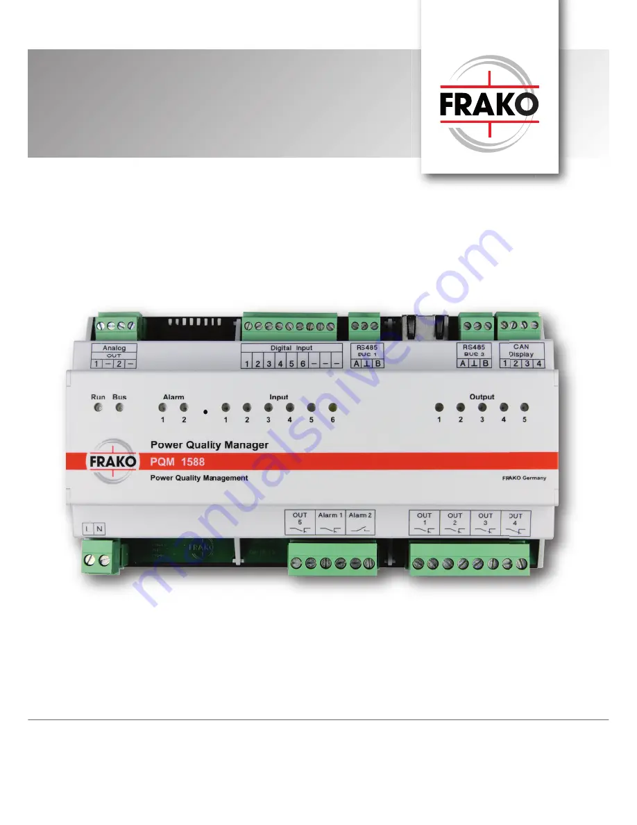
Power Quality Manager
PQM 1588Operating Manual
FRAKO Kondensatoren- und Anlagenbauwww.frako.com
Page 1: ...Power Quality Manager PQM 1588 Operating Manual FRAKO Kondensatoren und Anlagenbau www frako com...
Page 2: ...1 Alarm 1 Relays 15 5 3 2 Alarm 2 Relays 15 5 3 3 OUT 1 to OUT 5 Relays 15 5 4 RS 485 15 5 4 1 RS 485 BUS 1 Modbus RTU 16 5 4 2 RS 485 BUS 2 FRAKO Starkstrombus 17 5 5 Digital inputs 17 5 6 Analogue o...
Page 3: ...1 Installation 11 Figure 2 PQM connections 12 Figure 3 Bus connections 16 Figure 4 Digital inputs on PQM1588 17 Figure 5 Opening the web page for the S0 inputs 18 Figure 6 Analogue outputs 18 Figure 7...
Page 4: ...surance Institutions In other countries the equivalent local regulations must be followed Installation commissioning modifications and retrofitting may only be carried out by appropriately qualified p...
Page 5: ...ly reduced by observing the above safety precautions The user must ensure that all operators are familiarized with this operating manual and follow it at all times This operating manual must be read t...
Page 6: ...ult in death or serious injury DANGER Indicates an immediate danger of electric shock that if not avoided can result in death or serious injury Notes for the correct functioning of the instrument CAUT...
Page 7: ...witches DIP switches 8 DIP switches Annunciators LEDs 15 LEDs Design data Dimensions W H D 296mm 260mm 133mm casing Mounting Standard 35mm DIN rail as per EN 50022 Weight approx 0 4kg without packagin...
Page 8: ...ower Quality Manager collects and records data from the power quality management sys tem Alarms are also detected recorded and forwarded The data acquisition process requires system points which can b...
Page 9: ...Service functions Ongoing development of the PQM 1588 has endowed this instrument with a growing number of service functions and applications When required these can be enabled at the instrument websi...
Page 10: ...S 1 configuration If the PQM 1588 is to serve as gateway for the Modbus RTU bus it must not be configured for the data acquisition function Configuration is carried out in SYSTEM SW part of the FRAKON...
Page 11: ...e instrument base Figure 1 Mounting DANGER To avoid accidents the following must be observed The PQM 1588 must be installed in accordance with its intended use before power is switched on All the conn...
Page 12: ...power supply voltage exceeds the level specified in this operating manual and stated on the instrument this may cause damage to the PQM 1588 Consequential damage to other parts of the installation is...
Page 13: ...damage to the PQM 1588 and the electrical installation DANGER To avoid accidents the following must be observed At the PQM 1588 installation site e g control cabinet enclosure all wires and stranded...
Page 14: ...as specified in this manual The maximum operating voltage across the relay contacts as specified in Section 2 Technical Data When work is carried out on the instrument terminals and connecting cables...
Page 15: ...rm relay 2 is an NO normally open type Unlike alarm relay 1 it is not bistable During opera tion with no interruptions to the power supply its contacts remain closed In the event of a fault they open...
Page 16: ...bus RTU Connections are made to the terminals A and B of the connector marked RS 485 BUS 1 A signifies R D T D the Minus signal line B signifies R D T D the Plus signal line signifies chassis signal g...
Page 17: ...lines no longer than 2m Star topologies can be constructed using an EMB 1101 Repea ter available as an accessory The total length of the bus should not exceed 1200m An EMB 1101 Repeater must be instal...
Page 18: ...supply the power required for their output signals Figure 6 Analogue outputs The DIP switches 8 and 7 can be set to select the outputs as current or voltage signals Analogue outputs DIP switch OFF ON...
Page 19: ...above instructions are followed and the precautions specified in Section 1 2 Safety instructions are taken the risk of damaging equipment and assets or endangering life and limb can be significantly r...
Page 20: ...n and the PQM 1588 started up 6 2 Functional checkout When the power is switched on it takes several seconds before the PQM 1588 starts up This is indicated by all the LEDs lighting up and then after...
Page 21: ...twork settings Section 7 2 2 can resolve the situation 7 2 1 User network settings Network settings by DHCP In this case the following procedure can be used to determine the IP address IP via DNS The...
Page 22: ...The instrument website is accessed at the IP address of the PQM 1588 which can be entered in a browser e g http 192 168 0 60 or http pqm snXXXXXX where XXXXXX is the serial number of the instrument w...
Page 23: ...r the desired second IP address in the appropriate box Enter the associated subnet mask in the appropriate box With this configuration the PQM can be accessed by two different IP networks in the same...
Page 24: ...firmware is stated against Firmware Release in the table see below Figure 8 Firmware update NOTE The configuration function described in this section 7 3 2 Configuration Firmware update is available f...
Page 25: ...s by means of drop down menus The Send configuration button must be clicked to complete the process and implement the configuration The PQM 1588 is restarted when necessary 7 3 4 1 RS 485 BUS 1 config...
Page 26: ...The PQM 1588 has 6 inputs for the reception of pulses or statuses Typical sources of the pulses are a counter with pulse output signal an analogue frequency converter or a volt free contact for signa...
Page 27: ...PQM S0 counter module This first page shows the momentary condition the momentary derived variable and the non resettable counter total for each individual input The derived variable is calculated fro...
Page 28: ...clicking the Copy button Note that the entries at Name and Name of derived variable are not copied 4 When all the inputs have been configured the settings must then be transferred to the PQM 1588 by...
Page 29: ...n then be selected in a file upload dialogue This should normally have the extension JSON but it is not the file name extension that is crucial but its content If it is not a valid configuration file...
Page 30: ...m as counter units and a pulse value of 1000 pulses per m the multiplier will be 0 001 m per pulse Parameters for derived variable calculation The derived variable calculation is used when a counter o...
Page 31: ...frequency Value of the measured variable at the transducer s minimum pulse frequency Maximum pulse frequency Upper pulse frequency of the transducer Variable at maximum pulse frequency Value of the m...
Page 32: ...tory and normally does not need to be changed Counter added to or subtracted from group n The counter reading of each of the 6 inputs can be added to or subtracted from one of the 3 available group co...
Page 33: ...e Momentary state taking into account input inversion Momentary power flow etc pulses time Non resettable energy counter Figure 17 Web page for instrument S0 inputs To show all the measured values cli...
Page 34: ...ion figure is arrived at by periodically subtracting the most recently read pulse coun ter total from the momentary total and multiplying the difference by the pulse value Wdiff Counter_Mul Counter_Im...
Page 35: ...the password which consists of the last four numerals of the PQM 1588 s serial number 4 Click the Send reset command button to execute the reset If the correct password has been entered the message OK...
Page 36: ...em must be locked out to prevent its being inadvertently switched on again The immediate vicinity must be covered All connections must be checked to verify that they are no longer live Power must not...
Page 37: ...t be disconnected from the instrument All disconnected cables must be individually isolated and insulated and measures must be taken to prevent their inadvertent contact with live components or electr...
Page 38: ...red in a clean dry and dust free location The storage temperature must be within the range 20 C to 80 C 10 3 Disposal Any electronic instrument that is no longer required must be disposed of in an env...
Page 39: ...net as described in Section 4 Mounting the instrument All voltages applied to the instrument must never exceed the limits specified in the technical data The ambient temperatures must always be within...
Page 40: ...EMS Components Measuring Instruments and Network Analysers Power Quality EMS ISO 50001 FRAKO Kondensatoren und Anlagenbau GmbH Tscheulinstra e 21a D 79331 Teningen Tel 49 7641 453 0 Fax 49 7641 453 5...