USER MANUAL
TVNext
TM
(NN01-054)
Last updated on June 2020
© 2020 FRACTUS ANTENNAS, S.L. -
11
5.
ASSEMBLY PROCESS
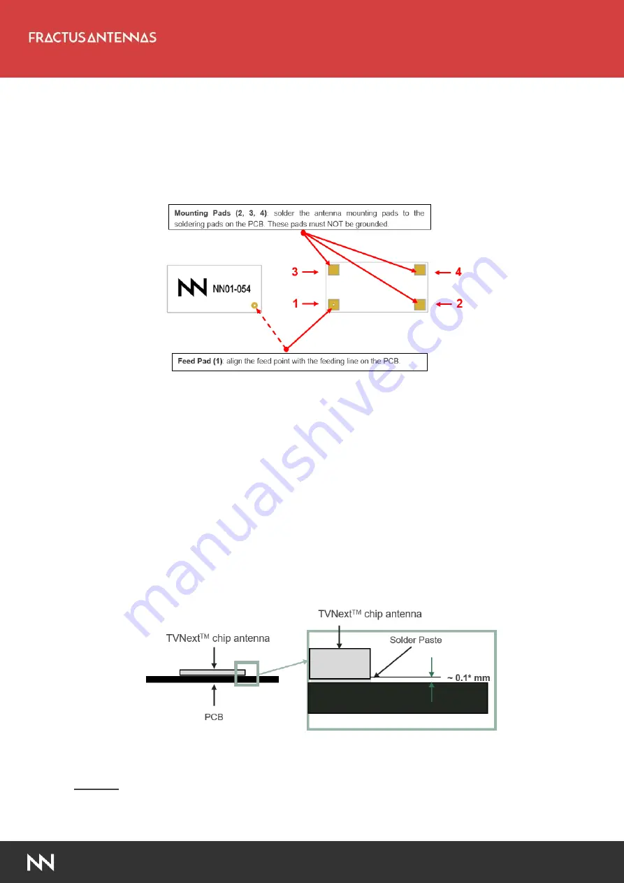
shows the back and front view of the TVNext
TM
VHF antenna, and indicates the
location of the feeding point and the mounting pads:
Figure 5
–
Pads of the TVNext
TM
VHF chip antenna.
As a surface mount device (SMD), this antenna is compatible with industry standard soldering
processes. The basic assembly procedure for this antenna is as follows:
1.
Apply a solder paste to the pads of the PCB. Place the antenna on the board.
2.
Perform a reflow process according to the temperature profile detailed in Table 3, Figure 7
on page 12.
3.
After soldering the antenna to the circuit board, perform a cleaning process to remove any
residual flux. Fractus Antennas recommends conducting a visual inspection after the
cleaning process to verify that all reflux has been removed.
The drawing below shows the soldering details obtained after a correct assembly process:
Figure 6
–
Soldering Details.
NOTE(*):
Solder paste thickness after the assembly process will depend on the thickness of the
soldering stencil mask. A stencil thickness equal to or larger than
127 microns (5 mils)
is
required.


