background image

31

ENGLISH

5.2.3 NETWORK MENU

NETWORK

IP ADDRESS

Enabling/disabling

DHCP function

Setting the module IP

address

On

Off

DHCP

SUBNET Mask

Setting the module

SUBNET Mask

DEFAULT GATEWAY

Setting the module

DEFAULT GATEWAY

IP ADDRESS

xxx.xxx.xxx.xxx

__.xxx.xxx.xxx

xxx.__.xxx.xxx

xxx.__.xxx.xxx

value

xxx.x xx.__.xxx

xxx.x xx.__.xxx

value

xxx.x xx.x xx.__

xxx.x xx.x xx.__

value

Exit by

__.xxx.xxx.xxx

value

SUBNET Mask

xxx.x xx.x xx.x xx

Exit by

DEFAULT GATEWAY

xxx.x xx.x xx.x xx

Exit by

Increase/decrease by using
the TPE arrow keys or enter
the v alue directly from the
keyboard.

Increase/decrease by using
the TPE arrow keys or enter
the v alue directly from the
keyboard.

Increase/decrease by using
the TPE arrow keys or enter
the v alue directly from the
keyboard.

__.xxx.xxx.xxx

xxx.__.xxx.xxx

xxx.__.xxx.xxx

value

xxx.x xx.__.xxx

xxx.x xx.__.xxx

value

xxx.x xx.x xx.__

xxx.x xx.x xx.__

value

__.xxx.xxx.xxx

value

__.xxx.xxx.xxx

xxx.__.xxx.xxx

xxx.__.xxx.xxx

value

xxx.x xx.__.xxx

xxx.x xx.__.xxx

value

xxx.x xx.x xx.__

xxx.x xx.x xx.__

value

__.xxx.xxx.xxx

value

Confirm the settings by pressing the 


 key; save the settings by

pressing the S key after the modules programmation.

0

65534

WEBSERVER PORT

WARNING: not use

the HTTP port already

occupied by some

others software

process running

Summary of Contents for SIG7710

Page 1: ...ISTRUZIONI PER L USO OPERATING INSTRUCTIONS INSTRUCTIONS D EMPLOI INSTRUCCIONES DE USO INSTRUÇÕES DE FUNCIONAMENTO BETRIEBSANLEITUNG SIG7710 QPSK DVB IP STREAMER ...

Page 2: ...ns of EN 50083 1 and not to connect the Sub rack or the rack to the protective earth PE of the supply mains IMPORTANT Never remove the product cover parts at hazardous voltage could be accessible when the product case is opened Only instructed and authorized persons can open the product In case of failure do not try to repair the product otherwise the guarantee will no longer be valid 2 PRODUCT DE...

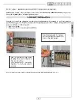
Page 3: ...ies as per the following photos Take the module out of its packaging and install it in the wanted position The packing contains the following parts SIG7710 module Fast jumper for the interconnection KPR41 To remove the module use the handles included in the New Headline 19 sub rack Fig 1 Fig 2 After the insertion fix the modu le using the screws contained in the accessory bag It s a plug and play ...

Page 4: ...summarizing table Green LED Red LED Meaning OFF Receiver off Flashing ON Receiver boot ON Flashing The receiver is supplied properly but it is not locked ON OFF The receiver is supplied properly and is locked ON ON The receiver is supplied properly but there is an internal fault Flashing ON if a fault is present OFF if it is locked Flashing if it is not locked Receiver interrogation Green LINK Eth...

Page 5: ...IP SAT HEAD Line SIG7710 IP SAT HEAD Line SIG7710 IP SAT HEAD Line SIG7710 IP SAT HEAD Line SIG7710 IP KPR41 FR PENTA85 DFP85 CHVU4ZN LAN PC LCD IP TV HEAD Line 01 SIG7901 HEAD Line SIG7904 HEAD Line SIG7904 HEAD Line SIG7904 HEAD Line SIG7904 HEAD Line SIG7904 SIG7710 SIG7904 LCD 10 00 IP TV ...

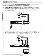
Page 6: ...to the module and enter all the configurations through the integrated web browser interface use a PC with a network adapter Ethernet card and an Ethernet CAT 5E crossover cable refer to the PRO GRAMMING INSTRUCTIONS SIG7710 WEB MANAGEMENT PROCEDURE 1 2 SAT HEAD Line SIG7730 IP SAT HEAD Line SIG7730 IP SAT HEAD Line SIG7730 IP SAT HEAD Line SIG7730 IP SAT HEAD Line SIG7730 IP SAT HEAD Line SIG7730 ...

Page 7: ...ged To modify this setting refer to the GENERAL MENU OF THE TPE TPE SETUP LANGUAGE Moreover it is essential to verify that the set timeout is equal to 30 To verify this setting refer to the TPE GENERAL MENU TPE SETUP TIMEOUT COM IMPORTANT Press the key of the TPE to save the set parameters If the key is not pressed within 5 minutes from the last modification the set data will be lost and the previ...

Page 8: ...onfirm the settings by pressing the key save the settings by pressing the S key after the modules programmation INPUT MEASURES NETWORK Setting the input parameters Measurements of the input and output signal NETWORK MENU see page 31 INPUT MENU see page 32 MEASURES MENU see page 35 SIG 7710 OUTPUT Setting the output parameters OUTPUT MENU see page 34 Confirm the settings by pressing the key save th...

Page 9: ...he value directly from the keyboard Increase decrease by using the TPE arrow keys or enter the value directly from the keyboard Increase decrease by using the TPE arrow keys or enter the value directly from the keyboard __ xxx xxx xxx xxx __ xxx xxx xxx __ xxx xxx value xxx xxx __ xxx xxx xxx __ xxx value xxx xxx xxx __ xxx xxx xxx __ value __ xxx xxx xxx value __ xxx xxx xxx xxx __ xxx xxx xxx __...

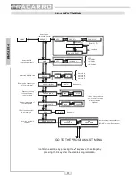
Page 10: ...se decrease from TPE by using the arrow keys or enter the value directly from the keyboard IF frequency setting of the transponder to be received SYMBOL RATE 1000 40000 FEC AUTO Read only Symbol rate setting of the transponder to be received FEC of the transponder to be received CHANNEL LIST 1 N PROGRAM 1 N N PROGRAM N Not available transponder not synchronized NONE service ID not present List of ...

Page 11: ...eyboard PCR PID PID PCR of the PID PCR of the selected selected program program VIDEO PID PID VIDEO of the PID VIDEO of the selected selected program program AUDIO PID PID AUDIO of the PID AUDIO of the selected selected program program Decrease value from the TPE digit keyboard TELETEXT PID PID TELETEXT of the PID TELETEXT of the selected selected program program SERVICE TYPE Type Type of of selec...

Page 12: ... value directly from the keyboard GROUP 12 Enter by RTP LAYER ENABLE GROUP MULTICAST PORT xxxx 1024 65535 ON OFF ON OFF MULTICAST IP xxx xxx xxx xxx Exit by The maximum MULTICAST GROUP available are 12 MULTICAST IP reading MULTICAST PORT reading __ xxx xxx xxx xxx __ xxx xxx xxx __ xxx xxx value xxx xxx __ xxx xxx xxx __ xxx value xxx xxx xxx __ xxx xxx xxx __ value __ xxx xxx xxx value Confirm th...

Page 13: ...he headend timeout value must be 30 Regulation of the TPE display contrast Restore the TPE default settings Italian English English Italiano Deutsch Français Espanol Portuguese 9600 115200 1 30 Increase decrease from TPE by using the arrow keys or enter the value directly from the keyboard 0 31 YES V NO X LANGUAGE 9600 19200 38400 57600 115200 BAUD RATE 232 9600 115200 9600 19200 38400 57600 11520...

Page 14: ...fter searching the main menu can be seen from the NAVIGATION function COPY Export the headend configuration to another one SIG7710 Refer to the SIG7710 general programming menu Yes V NO X SIG7710 All modules Restart the module KTP EMULATION KTP EMULATION V OUTPUT Emulation of the KTP programmer The function is not available for the programming of the SIG7710 module NAVIGATION OSD not available Yes...

Page 15: ...ernet browser Recommended Browser Internet Explorer 4 Enter the IP associated to the SIG7710 in the address bar the following HOME PAGE is displayed Select the language for the WEB Interface English Français Deutsch Italian Espanol Portugues From this menu the following options can be selected HOME Initial page of the integrated WEB configuration device INPUT Input parameters setting and measureme...

Page 16: ...nd Password default setting Username admin Password stream_77 After setting all the parameters confirm them with the SAVE command Reset an IP address belonging to the same sub network in the network card of the local PC that is used for programming 6 Enter the INPUT menu for the settings relevant to the satellite transponder selections to modify the settings for the first time it is necessary for ...

Page 17: ...ition Symbol Rate Setting the Symbol Rate of the chosen transponder After setting all parameters confirm them with the SAVE control After about 10 seconds from the PRO GRAM LIST menu it is possible to display all the programs contained in the selected transponder 7 Enter the MULTICAST menu to define and set all parameters relevant to the MULTICAST groups After setting the parameters confirm them w...

Page 18: ...Layer enabling disabling the Real Time Protocol used in the distribution of the Audio Video contents on IP disable for default Enable Enabling disabling the Multicast group WARNING the IP addresses selected for multicasting must be chosen within the 224 0 1 1 239 255 255 255 range To set addresses and Multicast ports correctly see the RFC regulations and the network administrator where the SIG7710...

Page 19: ...lticast group for each program c To activate the program in Multicasting transmission select the send control the program status will turn from send into stop and the bit rate associated to the program will change from 0Kbit s to the typical bit rate value associated to the program see the following image IMPORTANT for the proper functioning of the module is required not to exceed the 20Mbit s max...

Page 20: ...TE Presets are available for easy and quick SIG7710 settings see follow menù 6 CONNECTION OF THE SIG7710 MODULE TO THE LOCAL NETWORK After programming the module can be connected to the local LAN network by the CAT 5E patch cord Alla rete LAN SAT HEAD Line SIG7710 IP SAT HEAD Line SIG7710 IP SAT HEAD Line SIG7710 IP SAT HEAD Line SIG7710 IP SAT HEAD Line SIG7710 IP SAT HEAD Line SIG7710 IP KPR41 F...

Page 21: ...the proper management from the remote location These settings will be carried out by the administrator of the network where the encoder will be installed It is possible to manage via WEB all the SIG7710 included in the headend to verify the proper functioning to carry out the reprogramming remotely Such operations are possible only after the module configurations as indicated in previous chapters ...

Page 22: ...he LAN too high Turn off one or more streaming programs Proceed with the SIG7710 module settings Re enable the programs again 1 2 3 Impossibile IP address changing with TPE High Multicast traffic gener ated by the module present on the LAN Unplug the network intercon nection patch cable make changes Restore the link 1 2 3 The selection audio pro gram instead of video pro gram has a slight freezing...

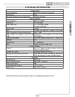
Page 23: ... the frequency and level of the input signal LNB remote feeding 0 14 18V 0 22KHz 200mA 14V 100mA 18V DiSEqC 1 0 Symbol rate 1 40 Msym s FEC Auto 1 2 2 3 3 4 5 6 7 8 OUTPUT SIGNAL Output Up to 12 digital encoded program in IP with single multicast address MPEG information Available MPEG2 information Supported transmission protocols UDP RTP SAP SDP PID filtering PSI SI par sing Regeneration of PAT a...

Reviews: