


15
ENGLISH
32
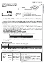
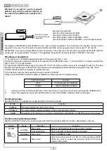
WL04MB
Magnetic contact bathroom
Z4
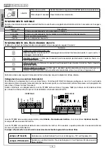
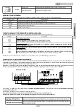
In this case, in the cell “Device” are listed all the devices acquired; in “position” the position of installation and in “Zone” the
number of the zone where they are placed.
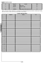
TABLE OF DEVICES
N°
Device
Position
Zone
1
2
3
4
5
6
7
8
9
10
11
12
13
14
15
16
17
18
19
20
21
22
23
24
25
26
27
28
29
30
31
32
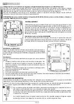
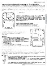
SAFETY WARNINGS
The system must be installed by qualified operators, in compliance with current national and local safety laws.
Installation warnings: In compliance with European Directive 2004/108/EC (EMC), the system must be installed using de-
vices, cables and accessories that comply with the requisites established by the Directive for permanent installations.
The product must not be exposed to dripping or splashing and thus it shall be installed indoors, in a dry place.
IMPORTANT: Only trained and authorised personnel are allowed to work on the system for the connections as described in
the instruction manual.
In the case of a fault, do not attempt to repair the product as it would render the guarantee invalid.
It is advisable to periodically check that the alarm system is in perfect working order; however a reliable electronic alarm
system does not prevent intrusion, theft, fire or other events but helps to reduce the risk of them occurring.
CONFORMITY WITH EUROPEAN DIRECTIVES - Fracarro Radioindustrie SpA declares that the product conforms to the
essential requisites and other permanent provisions established by the directive 1999/5/EC (RTTE - Radio and Telecom-
munications Terminal Equipment).