20
ENGLISH
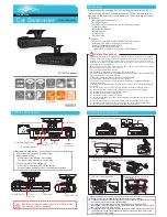
Mount Adaptor
The adaptor can be attached onto the top or the bottom of the unit.
Auto Iris Lens Connector (4-pin type)
The lens connector supplies the auto-iris lens (not supplied) with DC control signal.
PIN NO.
VIDEO
DC
1
DC + 12V
CONTROL -
2
NC
C
3
IRIS
DRIVE +
4
GND
DRIVE -
and
Video Connector
Video can be outputted via this connector. (75
Ω
).
Iris Mode Selection Switch
Select DC or VIDEO mode according to the lens.
OSD Control Buttons
ENTER button
UP & DOWN buttons
LEFT & RIGHT buttons
Power Input Indicator Light
When the camera is connected to a power supply, the indicator light will be on.
Power Input Terminal
Connect the power supply of 12Vdc or 12Vdc/24Vac (10.8Vdc~39Vdc/24Vac).
3. OSD OPERATION
3.1 OSD Control Buttons
Button 1
MENU/ENTER Button
Button 4
Button 2
Button 3
1. UP - Use this button to move the cursor upwards to the desired item.
2. RIGHT - Use this button to move the cursor to the right to select or to adjust the parameters of the
selected item. The parameter increases when the right button is pressed.
3. DOWN - Use this button to move the cursor downwards to the desired item.
4. LEFT - Use this button to move the cursor to the left to select or to adjust the parameters of the se-
lected item. The parameter decreases when the left button is pressed.
5. ENTER - Use this button to display the main menu, to confi rm and to enter the submenus when they’re
available. Items with the symbol “ ” in the end contain sub-menus. For further settings of those items,
select the desired item with the button
or
and press the ENTER button to bring up the sub-menu
and edit.


