Website : www.endeavourtools.com.au
Email support : [email protected]
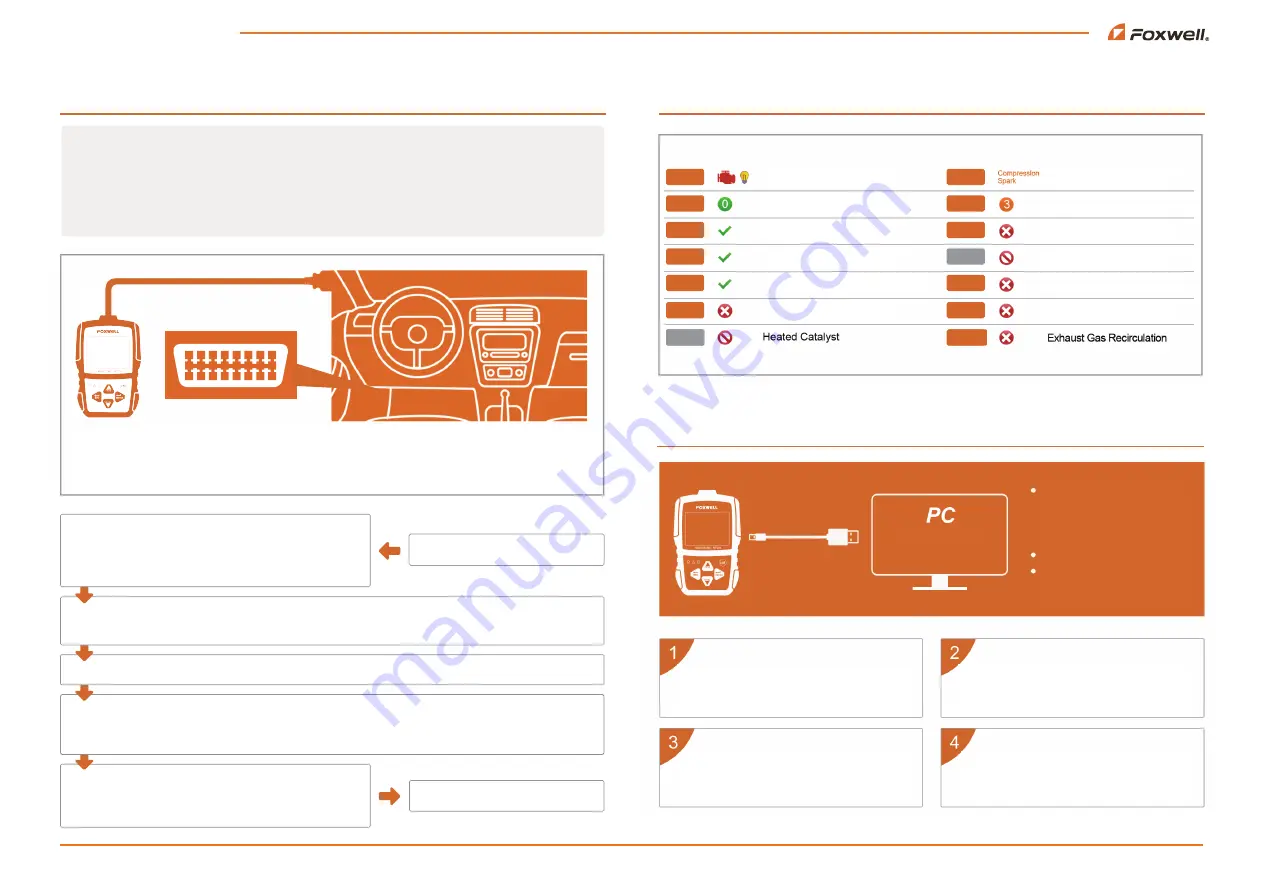
How to Use This Code Reader
Retrieve I/M
Updating
MIL
DTC
MIS
FUE
CCM
CAT
HCAT
IGN
Pd DTC
EVAP
AIR
O2S
HRT
EGR
Malfunction Indicator Lamp
Diagnostic Trouble Codes
Misfire
Fuel System
Comprehensive Component Monitor
Catalyst
Ignition
Pending Codes
Evaporative System
Intake Air System
Oxygen Sensor
Oxygen Sensor Heater
Do not disconnect the code reader
from the computer or power off
the computer during the update
process
No registration required
Windows 8 onwards supported
Download the update tool NT Wonder and
install it.
Click <Update online> or <Update offline>
to start updating according to the software
version conditions.
Connect the code reader to your
computer with the USB cable.
An Update Finished message displays
when the update is completed.
FOXWELLTECH.US
Enter “I/M Readiness”.
Turn on the ignition of your car
O2 Monitor Test, On-Board Monitor Test, Component Test.
The availability of these tests are vehicle dependent, and
may not be available on all vehicles.
Before starting diagnosis, please ensure:
1. The ignition switch is turned to the ON position.
2. That the vehicle's engine is off.
3. The vehicle battery voltage is between 12-14 volts.
Don't connect or disconnect the code reader while the ignition is on or the engine is running.
4. The scanner is correctly connected to the vehicle.
Enter “View Freeze Frame”. This is a snapshot of critical vehicle operating conditions automatically recorded
by the on-board computer at the time the DTC ( Diagnostic Trouble Code) was recorded. This data can also
help identify faulty sensors.
Enter “Live Data”, graphing selected live data will help locate faulty sensors.
Choose “Read Codes”- Choose each selection to check. Pending Codes means the codes will need to be
confirmed after several driving cycles.
In the main menu, ENTER OBDII/EOBD. The code
reader will start scanning. Wait several seconds, then
choose “yes/no” with the right arrow key, and enter the
Diagnostic Menu.
QUICK START GUIDE
Insert the OBD interface
1
2
3
4
5
6
7
8
9 10 11 12 13 14 15 16
OBDII Connector and Pinout
1.Vendor Option / 2. SAE J / 3. Vendor Option / 4. Chassis Ground / 5. Signal Ground / 6. CAN(J-2234)High
7. ISO 9141-2K-Line / 8. Vendor Option / 9 . Vendor Option / 10. SAE J1850BUS- / 11. Vendor Option / 12. Vendor Option
13. Vendor Option / 14. CAN(J-2234)Low / 15. ISO 9141-2Low / 16. Battery Power
Chat support - visit www.endeavourtools.com.au


