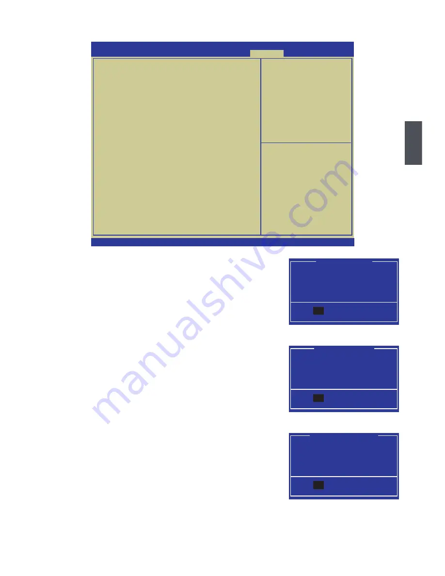
background image

39

3

Save & Exit

 Save Changes and Reset 

If you select this option and press <Enter>, a message will be 

displayed in the center of the screen. 

Select [Yes] to save your changes and reset computer, select 

[No] or <ESC> to return to the main menu.

 Discard Changes and Reset 

If you select this option and press <Enter>,  a message will be 

displayed in the center of the screen. 

Select [Yes] to exit setup utility and reset computer without 

saving your modiications, select [No] or <ESC> to return to the 

main menu.

 Restore Defaults

Optimal defaults are the best settings of this motherboard. 

Always load the Optimal defaults after updating the BIOS or 

after clearing the CMOS values.

Select this option and press Enter, it will pop out a dialogue 

box to let you load the defaults. Select <Yes> and then press 
<Enter> to load the defaults. Select <No> and press <Enter>, it 

will not load. 

By this default, BIOS have set the optimal performance 

parameters of system to improve the performances of system 

components. But if the optimal performance parameters to be set cannot be supported by your 

hardware devices (for example, too many expansion cards were installed), the system might 

fail to work.

Save configuration and reset?

Yes                          No

Save . Reset


Yes

Reset without saving?

Yes                          No

Reset Without Saving


Yes

Load Optimized Defaults?

Yes                          No

Load Optimized Defaults

Yes


Save Changes and Reset

    Discard Changes and Reset


Restore Defaults


Boot Override

Version 2.02.1205. Copyright (C) 2010 American Megatrends, Inc.

: Select Screen

: Select Item

Enter: Select

+/-: Change Opt.

F1:  General Help

F2:  Previous Values

F3: Optimized Defaults

F4: Save � Exit

ESC: Exit

Reset the system after saving
the change.

Aptio Setup Utility - Copyright (C) 2010 American Megatrends, Inc.


Main  Advanced  Chipset  Boot  Power  Health   Security  Save . Exit

Save . Exit

Summary of Contents for H67S Series

Page 1: ...л чит т нич ю н льт цию гл т чн Б з вы дны www sotmarket ru д бн я инф м ция т в тзывы бз ы и ы Инструкция для платы Foxconn H67S материнской Перейти в карточку товара 8 800 775 98 98 ...

Page 2: ...H67S Series Motherboard User s Manual ...

Page 3: ... that this product may not be treated as household waste By ensuring this product is disposed of correctly you will help prevent potential negative consequences for the environment and human health which could otherwise be caused by inappropriate waste handling of this product For more detailed information about recycling of this product please contact your local city ofice your household waste di...

Page 4: ...adio disturbance characteristics of information technology equipment EN 61000 3 2 2000 Electromagnetic compatibility EMC Part 3 Limits Section 2 Limits for harmonic current emissions equipment input current 16A per phase EN 61000 3 3 A1 2001 Electromagnetic compatibility EMC Part 3 Limits Section 2 Limits of voltage luctuations and licker in low voltage supply systems for equipment with rated curr...

Page 5: ...cturer HON HAI PRECISION INDUSTRY COMPANY LTD Address 66 CHUNG SHAN RD TU CHENG INDUSTRIAL DISTRICT TAIPEI HSIEN TAIWAN R O C Supplementary Information This device complies with Part 15 of the FCC Rules Operation is subject to the following two conditions 1 this device may not cause harmful interference and 2 this device must accept any interference received including interference that may cause u...

Page 6: ... the power please make sure the power supply AC input voltage setting has been conigured to the local standard To prevent damage to the motherboard do not allow screws to come in contact with the motherboard circuit or its components Also make sure there are no leftover screws or metal components placed on the motherboard or within the computer casing If you are uncertain about any installation st...

Page 7: ...sion Card 13 Install other Internal Connectors 14 Jumpers 17 Chapter 3 BIOS Setup Enter BIOS Setup 20 Main 21 Advanced Advanced 23 Chipset 30 Boot 34 Power Power 35 Health Health 37 Security 38 Save Exit Save Exit 39 Chapter 4 CD Instruction Utility CD content Utility CD content 42 Install driver and utility 43 FOX ONE Main Page 46 CPU Control 50 Frequency Control 52 Limit Setting 53 Voltage Contr...

Page 8: ...echnical Support Website http www foxconnchannel com Support Website http www foxconnsupport com Worldwide Online Contact Support http www foxconnsupport com inquiry aspx CPU Support List http www foxconnsupport com cpusupportlist aspx Memory VGA Compatibility List http www foxconnsupport com complist aspx Support ...

Page 9: ...ou need for break through performance With advanced overclocking capability and a range of connectivity features for today multi media computing requirements H67S enables H67S enables enables you to unleash more power from your computer This chapter includes the following information Product Speciications Layout Back Panel Connectors ...

Page 10: ...chipset Support 1 x SATA 2 0 2 x SATA 3 0 connectors 1 x E SATA connector 300MB s data transfer rate SATA 2 0 600MB s data transfer rate SATA 3 0 Support hot plug and NCQ Native Command Queuing USB Support hot plug Support up to 10 x USB 2 0 ports 6 rear panel ports 2 onboard USB headers supporting 4 extra ports Support USB 2 0 protocol up to 480Mb s Internal Connectors 1 x 24 pin ATX main power c...

Page 11: ... 8GB s 16GB s concurrent bandwidth Low power consumption and power management features Green Function Support EuP Function Support ACPI Advanced Coniguration and Power Interface Support S0 normal S1 power on suspend S3 suspend to RAM S4 suspend to disk and S5 soft off Bundled Software FOX ONE FOX LiveUpdate FOX LOGO FOX DMI Operating System Support for Microsoft Windows XP 7 Form Factor Mini ITX F...

Page 12: ...nector 3 Front Audio Connector 4 S PDIF_OUT Connector 5 MFG Jumper 6 PCI Express x16 Slot 7 Front USB Connectors 8 PCH Intel H67 9 SATA Connectors 10 Clear CMOS Jumper 11 Front Panel Connector 12 24 pin ATX Power Connector 13 LGA 1155 CPU Socket 14 DDR3 DIMM Slots 15 CPU Fan Header 16 System Fan Header 17 Speaker Connector 2 4 1 8 6 11 12 13 15 17 3 5 9 10 14 16 7 ...

Page 13: ...maximum resolution of 1920x1080p but the actual resolutions supported depend on the monitor being used 5 E SATA Port To connect external SATA device s to your system by expanding the internal SATA port s to the chassis back panel External SATA device shall provide power by its own 6 Audio Ports For the deinition of each audio port please refer to the table below DVI I Port LAN Port USB Ports PS 2 ...

Page 14: ...nection at up to 10 100 1000Mb s data rate LAN Type Left Active Right Link Status Description Status Description 1000M Off No Link Off No Link Green Blinking Data Activity Off 10Mb s Connection Green 100Mb s Connection Orange 1000Mb s Connection Active LED Link LED ...

Page 15: ...ut prior to any installation and read the contents in this chapter carefully This chapter includes the following information Install the CPU and CPU Cooler Install the Memory Install an Expansion Card Install other Internal Connectors Jumpers Please visit the following website for more supporting information about your motherboard CPU Support List http www foxconnsupport com cpusupportlist aspx Me...

Page 16: ...mmended that the system bus frequency be set beyond hardware speciications since it does not meet the standard requirements for the peripherals If you wish to set the frequency beyond the standard speciications please do so according to your hardware speciications including the CPU graphics card memory hard drive etc Hyper Threading Technology System Requirements Go to Intel s website for more inf...

Page 17: ...al cover on the CPU socket 3 Remove protective socket cover emove protective socket cover 5 When CPU is properly seated replace the metal cover and push the CPU socket lever back to its locked position 4 Check pin one marking triangle with the pin one corner of the CPU socket align the CPU notches with the socket alignment keys and gently put the CPU onto the socket 1 Release the CPU socket lever ...

Page 18: ...otherboard That s it 3 Check the solder side of the motherboard the push pin should be ixed as depicted in the picture 3 2 1 4 Attach the 4 wire CPU cooler connector to the CPU FAN header on the motherboard Release bolts of CPU cooler from motherboard 1 Turning the push pin bolt along with the direction of arrow counterclockwise 2 Pull the push pin straight up 3 Turning push pin clockwise to its d...

Page 19: ... memory It is recommended that memory of the same capacity brand speed and chips be used Always turn off the computer and unplug the power cord from the power outlet before installing the memory to prevent hardware damage Memory modules have a foolproof design A memory module can be installed in only one direction If you are unable to insert the memory switch the direction C A U T I O N It is reco...

Page 20: ...mory socket Place the memory module onto the socket then put your ingers on top edge of the module and push it down irmly and seat it vertically into the memory socket Step 2 The clips at both ends of the socket will snap into place when the memory module is securely inserted Before installing a memory module make sure to turn off the computer and unplug the power cord from the power outlet to pre...

Page 21: ...ided with the expansion card in your operating system Installing and Removing a PCI Express x16 Graphics Card Installing a Graphics Card Gently insert the graphics card into the PCI Express x16 slot Make sure the graphics card is locked by the latch at the end of the PCI Express x16 slot Removing the Card Push the latch at the end of the PCI Express x16 slot to release the card and then pull the c...

Page 22: ...to the connector and make sure it is secure 4 pin ATX 12 V Power Connector PWR2 Connect the 4 pin ATX 12V power supply to PWR2 and provides power to the CPU Pin Deinition Pin Deinition 1 3 3V 13 3 3V 2 3 3V 14 12V 3 GND 15 GND 4 5V 16 PS_ON Soft On Off 5 GND 17 GND 6 5V 18 GND 7 GND 19 GND 8 Power Good 20 NC 9 5V SB Stand by 5V 21 5V 10 12V 22 5V 11 12V 23 5V 12 3 3V 24 GND PWR1 24 13 12 1 We reco...

Page 23: ...or is used for S PDIF output USB Connectors F_USB1 2 In addition to the four USB ports on the rear panel this product also provides two 10 pin USB headers on its motherboard By connecting through USB cables with them user can quickly expand another four USB ports on the front panel Speaker Connector SPEAKER The speaker connector is used to connect speaker of the chassis F_USB 1 2 NC GND VCC D D D ...

Page 24: ...the LED is off This 2 pin connector is directional with sign Power Switch Connector PWR SW Connect to the power button on the front panel of the chassis Push this switch allows the system to be turned on and off rather than using the power supply button Fan Headers CPU_FAN SYS_FAN There are two main fan headers on this motherboard The fan speed can be controlled and monitored in PC Health Status s...

Page 25: ...rdous ESD Electrical Static Discharge problem Clear CMOS Jumper CLR_CMOS The motherboard uses CMOS RAM to store the basic hardware information such as BIOS data date time information hardware password etc Clear CMOS data is the fast way to go back to factory default when the BIOS settings were mistakenly modiied The steps to clear CMOS data are 1 Turn off the computer unplug the power cord from th...

Page 26: ...t It provides latest IT management features such as Intel AMT that allows to improve management of corporate assets Set the jumper to pins 1 2 you can enable the Intel Management Engine function Set the jumper to pins 2 3 you can disable the Intel Management Engine function Enable Default 1 2 3 Disable 1 2 3 MFG Before lashing BIOS ROM you need to set MFG jumper to pins 2 3 irst C A U T I O N ...

Page 27: ... want to change the default CMOS settings This chapter includes the following information Enter BIOS Setup Main Advanced Chipset Boot Power Power Health Health Security Security Save Exit Save Exit Since BIOS could be updated some other times the BIOS information described in this manual is for reference only We do not guarantee the content of this manual will remain consistent with the newly rele...

Page 28: ...ority and enable Quiet Boot feature here Power All the items related with Green function features can be setup through this menu Health This setup enables you to read change fan speeds and displays temperatures and voltages of your CPU System Security The Administrator User password can be set up through this menu to prevent unauthorized use of your computer If you set a password the system will a...

Page 29: ...with administrator password this item will dispaly Administrator Model Name This item shows the model name of this product model name of this product ME Version It displays the current ME version BIOS Version It displays the current BIOS version User can check this information and discuss with the ield service people if a BIOS upgrade is needed System Date Tue 10 12 2010 System Time 09 44 21 Acces...

Page 30: ...nd time CPU Brand Name It displays the current CPU name Total Memory This item displays the total memory size The size is depending on how many memory mod ules are installed in your system before powering on MAC Address This item displays the onboard LAN MAC Address ...

Page 31: ...guration Intel IGD SWSCI OpRegion USB Configuration onboard Device Configuration Version 2 02 1205 Copyright C 2010 American Megatrends Inc Aptio Setup Utility Copyright C 2010 American Megatrends Inc Advanced Chipset Boot Power Health Security Save Exit Main Advanced Select Screen Select Item Enter Select Change Opt F1 General Help F2 Previous Values F3 Optimized Defaults F4 Save Exit ESC Exit CP...

Page 32: ...te Disable Bit with anti virus irewall spyware removal e mail iltering software and other network security measures IT managers can free IT resources for other initiatives Intel Virtualization Technology Appears only when CPU supports Virtualization i e Intel Vanderpool Technology allows a platform to run multiple operating systems and applications in independent partitions or containers One physi...

Page 33: ... Limit 37 3 Core Ratio Limit 36 4 Core Ratio Limit 35 Version 2 02 1205 Copyright C 2010 American Megatrends Inc Aptio Setup Utility Copyright C 2010 American Megatrends Inc Advanced Advanced Select Screen Select Item Enter Select Change Opt F1 General Help F2 Previous Values F3 Optimized Defaults F4 Save Exit ESC Exit Enhanced Intel SpeedStep Technology Enhanced Intel SpeedStep technology EIST al...

Page 34: ...ght C 2010 American Megatrends Inc Advanced Advanced Select Screen Select Item Enter Select Change Opt F1 General Help F2 Previous Values F3 Optimized Defaults F4 Save Exit ESC Exit Select DVMT Mode used by Internal Graphics Device SATA Coniguration SATA Mode IDE Mode SATA Port1 Not Present SATA Port2 Not Present SATA Port3 Not Present E SATA Port Not Present Version 2 02 1205 Copyright C 2010 Ame...

Page 35: ...B Support This item is used to enable the support for USB devices on legacy OS If you have a USB keyboard or mouse set to enabled Enabled This option will enable the legacy USB support Disabled This option will keep USB devices available only for EFI applications Auto This option will disable the legacy support if no USB devices are connected USB Coniguration USB Devices 2 Hubs All USB Devices Ena...

Page 36: ...sable Azalia HD Audio Super IO Coniguration Super IO Coniguration Press Enter to go to submenu Onboard Device Coniguration Onboard LAN Controller Enabled Onboard LAN PXE OpROM Disabled Disabled Audio Coniguration Azalia HD Audio Enabled Enabled Super IO Configuration Version 2 02 1205 Copyright C 2010 American Megatrends Inc Aptio Setup Utility Copyright C 2010 American Megatrends Inc Advanced Adv...

Page 37: ...Device Mode This item is used to change the serial port mode Options are Normal and High Speed Super IO Coniguration Super IO Chip IT8772 IT8772 Serial Port 0 Coniguration Serial Port Enabled Device Settings IO 3F8h IRQ 4 Change Settings Auto Auto Device Mode Standard Serial Po Version 2 02 1205 Copyright C 2010 American Megatrends Inc Aptio Setup Utility Copyright C 2010 American Megatrends Inc A...

Page 38: ...pyright C 2010 American Megatrends Inc Select Screen Select Item Enter Select Change Opt F1 General Help F2 Previous Values F3 Optimized Defaults F4 Save Exit ESC Exit North Bridge Parameters Aptio Setup Utility Copyright C 2010 American Megatrends Inc Main Advanced Chipset Boot Power Health Security Save Exit Chipset ...

Page 39: ...stems and also improve performance of I O devices in virtualized environment These inherently helps IT managers reduce the overall total cost of ownership by reducing potential down time and increasing productive throughput by better utilization of the data center resources Initial Graphic Adapter This item is used to select which graphics controller is used as the primary boot device IGD Memory T...

Page 40: ...to go to its submenu Intel ME Subsystem Coniguration ME Version 7 0 0 1061 ME Subsystem Enabled Integrated Clock Chip Configuration Version 2 02 1205 Copyright C 2010 American Megatrends Inc Select Screen Select Item Enter Select Change Opt F1 General Help F2 Previous Values F3 Optimized Defaults F4 Save Exit ESC Exit ME Subsystem Help Aptio Setup Utility Copyright C 2010 American Megatrends Inc C...

Page 41: ... disable ICC Set Proiles Set Proile Index This item displays the ICC set Proile Index ICC OverClocking Press Enter to go to its submenu It used to change the Integrated Clock Control options Options are DIV 1S DIV 2S DIV3 DIV4 DIV 1NS DIV 2NS Integrated Clock Chip Coniguration ICC OverClocking Lib Version 7 0 0 27 Number of ICC Proiles 1 Current ICC Proile Index 0 ICC Enable Enabled ICC Set Clock ...

Page 42: ... Option Priorities Boot Option Priorities This item is used to set the the priorities of the boot devices Boot Coniguration Bootup Numlock State On Quiet Boot Enabled CSM16 Module Version 07 63 Boot Option Priorities Version 2 02 1205 Copyright C 2010 American Megatrends Inc Select Screen Select Item Enter Select Change Opt F1 General Help F2 Previous Values F3 Optimized Defaults F4 Save Exit ESC ...

Page 43: ...ping state is the lowest power longest wake latency sleeping state supported by ACPI In order to reduce power to a minimum it is assumed that the hardware platform has powered off all devices Platform context is maintained also called Suspend to Disk S5 The S5 state is similar to the S4 state except that the OS does not save any context The system is in the soft off state and requires a complete b...

Page 44: ...s used to enable disable the Onboard LAN to generate a wake up Resume by USB Devices This item is used to enable disable the USB keyboard or mouse to generate a wake up Resume by PCIE PME This item is used to enable disable a PCI Express device to generate a wake up Resume by RTC This item is used to enable disable RTC alarm event to generate a wake up RTC is system real time clock Energy using Pr...

Page 45: ...tion is used to enable or disable smart fan function Default value is Disabled Only when this option is enabled you can set some correlative parameters Smart Fan Automatic Mode is the principle igure of CPU smart fan function for your reference CPU Temperature 18 C System Temperature 29 C System Fan Speed N A CPU Fan Speed 2566 RPM CPU Vcore 0 972 V DRAM Voltage 1 560 V 12V SYS 12 384 V 5V SYS 3 0...

Page 46: ... Password Password Description If ONLY the Administrator s password is set then this only limits access to Setup and is only asked for when entering Setup If ONLY the User s password is set then this is a power on password and must be entered to boot or enter Setup In Setup the User will have Administrator rights The password must be 3 to 20 characters long Administrator Password User Password HDD...

Page 47: ...Enter to load the defaults Select No and press Enter it will not load By this default BIOS have set the optimal performance parameters of system to improve the performances of system components But if the optimal performance parameters to be set cannot be supported by your hardware devices for example too many expansion cards were installed the system might fail to work Save configuration and rese...

Page 48: ...40 3 Boot Override You can select the boot device through this item without changing the booting sequence in setup ...

Page 49: ...s that enhance the motherboard features This chapter includes the following information Utility CD content Install driver and utility FOX ONE FOX LiveUpdate FOX LOGO FOX DMI Note Because each module is independent so the section number will be reorganized and unique to each module please understand ...

Page 50: ... LAN Driver E Intel ME Interface Driver Intel ME Interface Driver 2 Software Utilities Use these options to install additional software programs FOX ONE is a very powerful user interface program which allows you to change your system setting without going to BIOS Some auto features help user to improve or overclock your system without being a computer literate Options for Windows XP A FOX ONE B FO...

Page 51: ... all the drivers for your system You must click Intel Chipset Driver to install it irst After that you can click One Click Setup and then choose the items you want to install or you can click on each individual driver to install it manually Visit Foxconn s Website Show Utilities Show Drivers Browse CD View the Utility Help iles Manual Installation Step by Step Automatic Installation by One Click D...

Page 52: ...44 4 Click here 2 Utility Use these options to install additional software programs And click Utility Help button to view the utility FOX ONE FOX LiveUpdate FOX LOGO FOX DMI help manual ...

Page 53: ...t Stepping will require you to calibrate the CPU s loading Click OK to proceed and start the Utility F I S is a feature of FOX ONE which can automatically adjust your CPU clock based on your current system loading Before you running the FOX ONE program the system parameters such as CPU clock voltage etc are controlled by BIOS settings After you run FOX ONE it will take over and the controlling rig...

Page 54: ...mplify the whole FOX ONE control panel to a smaller information bar i e Simple Mode as depicted below you can drag this bar to any place on your screen to help you monitoring system status Click here to go back to FOX ONE full screen Click here will drop the FOX ONE to Windows system tray Exit FOX ONE Show CPU Information Toolbar Alert Lamp Switch Button Exit Minimum Homepage Monitor Frequency Vol...

Page 55: ...t Click this button to exit the program Minimum Click this button to drop the FOX ONE to Windows system tray located at the lower right corner of your screen Homepage Click this button to visit Foxconn motherboard website http www foxconnchannel com Apply the changes Click the new skin picture to select the new skin Cancel the changes ...

Page 56: ... Simple Mode Messages such as CPU frequency voltage etc they can be displayed one by one in Simple Mode 3 F I S Calibration FOX Intelligent Stepping Optional This function will re calibrate the CPU s loading and it may take several minutes to proceed The FOX ONE calibration process will apply different loadings to your CPU record PWM IC voltage together with the CPU clock running at these loadings...

Page 57: ... After data is collected it will ask you to restart your computer now Later on when the FOX ONE program is activated and F I S feature in CPU Page is also enabled FOX ONE will automatically adjust your CPU clock according to your system loadings Loadings are like Power Gaming Data Mining etc ...

Page 58: ...eck the highest CPU clock you can use System will raise the CPU clock step by step until it hangs you can then push the RESET button on your PC panel to restart the system When system restarts run FOX ONE again it will display a recommended highest CPU clock for you click Yes to apply it A message informs you to push RESET button later if the system hangs inally Click Yes to continue Press Auto bu...

Page 59: ...ET button on the front panel of your system to restart the computer Run FOX ONE program again it will inform you the previous test found that 255MHz is the recommended CPU clock for your system Click Yes to apply it to your system Now your system is running at a CPU clock of 255MHz ...

Page 60: ...ts speed to a minimum The four benchmarks Power Gaming Data Mining Ofice and Energy Saving the references of their system loading were calculated and deined in the FIS Calibration option of Coniguration menu Select Auto CPU will automatically adjust its clock according to current system loading 3 Frequency Page Frequency Control This page lets you set memory and PCI Express frequencies by manual G...

Page 61: ...ert function Go to Limit Setting page Set high limit by dragging the lever Show current CPU temperature value Enable alert function when the CPU temperature is higher than high limit value Show current high limit value of the CPU temperature Set high limit by dragging the lever Show current system temperature value Enable alert function when the system temperature is higher than high limit value S...

Page 62: ...ert function Set low limit rpm by dragging the lever Show current CPU fan rpm value Enable alert function when the CPU fan runs slower than the low limit rpm value Show current low limit rpm value of CPU fan Set low limit rpm by dragging the lever Show current system fan rpm value Enable alert function when the system fan runs slower than low limit rpm value Show current low limit rpm value of sys...

Page 63: ...ge manually CPU voltage can be stepped up down by a unit of 12 5mV while memory is 0 05V step and North Bridge is 0 04V step Set low limit rpm by dragging the lever Show current FAN1 fan rpm value Enable alert function when the FAN1 fan runs slower than low limit rpm value Show current low limit rpm value of FAN1 fan Go to Voltage page Select the option you want to set Adjust by manual Reset the c...

Page 64: ...s you enable Smart Fan function or set the fan speed by manual When Smart Fan is selected you must use a 4 pin CPU cooler in your system Go to Fan page Set fan speed by dragging the lever Enable or disable smart fan function Apply the changes ...

Page 65: ...ws 2000 Windows XP 32 bit and 64 bit Windows 2003 32 bit and 64 bit Windows Vista 32 bit and 64 bit Windows 7 32 bit and 64 bit Using FOX LiveUpdate 1 Local Update 1 1 Local Update BIOS Information This page lets you know your system BIOS information please refer to the physical motherboard for detail Exit Toolbar Minimum Show current BIOS information Link to website ...

Page 66: ... ensure if you really want to continue click Yes to conirm A setup wizard will guide you to load a local BIOS ile to inish the operation You must remember from which directory to load your new BIOS ile with an extension of BIN for Award BIOS ROM for AMI BIOS before the setup wizard starts Key in a BIOS name Click here FOX LiveUpdate can automatically backup old BIOS before update This feature can ...

Page 67: ...ation 2 2 Online Update Update Driver This page lets you update your system drivers from Internet Click start it will search the new drivers from Internet Then follow the wizard to inish the update operation Click here Current information Search new BIOS from Internet Browse detailed information Update BIOS Close the window Select BIOS to update Click here Current information Search new drivers fr...

Page 68: ...rom Internet Then follow the wizard to inish the update operation Browse detailed information Install the selected driver Close the window Select the driver to update Click here Current information Search new utilities from Internet Browse detailed information Install the selected utility Close the window Select the utility to update ...

Page 69: ...ill search all new BIOS drivers utilities from Internet Then follow the wizard to inish the update operation Click here Current information Search all new BIOS drivers utilities from Internet Browse detailed BIOS information Close the window Browse detailed driver information Browse detailed utility information ...

Page 70: ...m Internet and if any qualiied item found it will pop out a message on the task bar to inform you to do the next step Double click on the icon as show below you can see the detailed information Double click here Apply the changes Reset to default value Click here Set auto search options Select search which kind of versions Set auto search the latest FOX LiveUpdate ...

Page 71: ...re System This page lets you set the location of download iles and auto backup BIOS determine if the FOX LiveUpdate can auto run when the system starts up Click here Set the location of download iles or auto backup BIOS Determine if the FOX LiveUpdate can auto run when the system starts up Apply the changes Reset to default value Prompt you to install the new FOX LiveUpdate ...

Page 72: ...out any interruption 4 About Help This page shows some information about FOX LiveUpdate Click here Select which BIOS ROM to lash Only available to motherboard with backup BIOS ROM Apply the changes Reset to default value Select to lash Boot Block Select to clear CMOS Click here Show information about FOX LiveUpdate We recommend that you had better keep the default setting unchanged to avoid any da...

Page 73: ...if you enable the BIOS Quiet Boot setting in Boot menu Supporting Operating Systems Windows 2000 Windows XP 32 bit and 64 bit Windows 2003 32 bit and 64 bit Windows Vista 32 bit and 64 bit Windows 7 32 bit and 64 bit Using FOX LOGO Main Page When you change Logo or delete current Logo the system will lash BIOS ile auto matically During this time please DO NOT shut down the application and the syst...

Page 74: ...ze and troubleshoot your motherboard if there is any problem occurred Supporting Operating Systems Windows 2000 Windows XP 32 bit and 64 bit Windows 2003 32 bit and 64 bit Windows Vista 32 bit and 64 bit Windows 7 32 bit and 64 bit Using FOX DMI Please operate this utility as the comments shows Click here to select the DMI Data format you need Click here to select the type you want to view ...

Page 75: ...л т з з любым д бным б м гл т чн я л жб дд ж и Д т в з з в в ии ф мл ни дит нл н з 2 мин ты м нии Д т в и л т вин и тзывы ции и ид и платы Foxconn H67S материнской Описание Характеристики Отзывы ...

Reviews: