background image

Chapter 3     BIOS Description

19

v

Supervisor/User Password

   The access rights and permissions associated with the supervisor password
   are higher than those of a regular user password. The supervisor password is
   used to authorize the capability to change BIOS setup options. The user pass
   word is used to authorize the capability to change non-critical BIOS setup
   options only, such as system date and system time. While the user password
   can be used to view the current CMOS settings, these settings can not be
   modified using the user password.
   When you select the Supervisor/User Password option, the following message
   will appear in the center of the screen, which will help you to set the password:

   Enter Password:

   Enter your password, not exceeding 8 characters, then press <Enter>.
    The password you entered will replace any previous password. When
   prompted, key in the new password and press <Enter>.

v

Change Supervisor Password

Press <Enter> to change password.

v

Onboard Audio

The option is used to enable or disable Onboard Audio or auto detection.

v

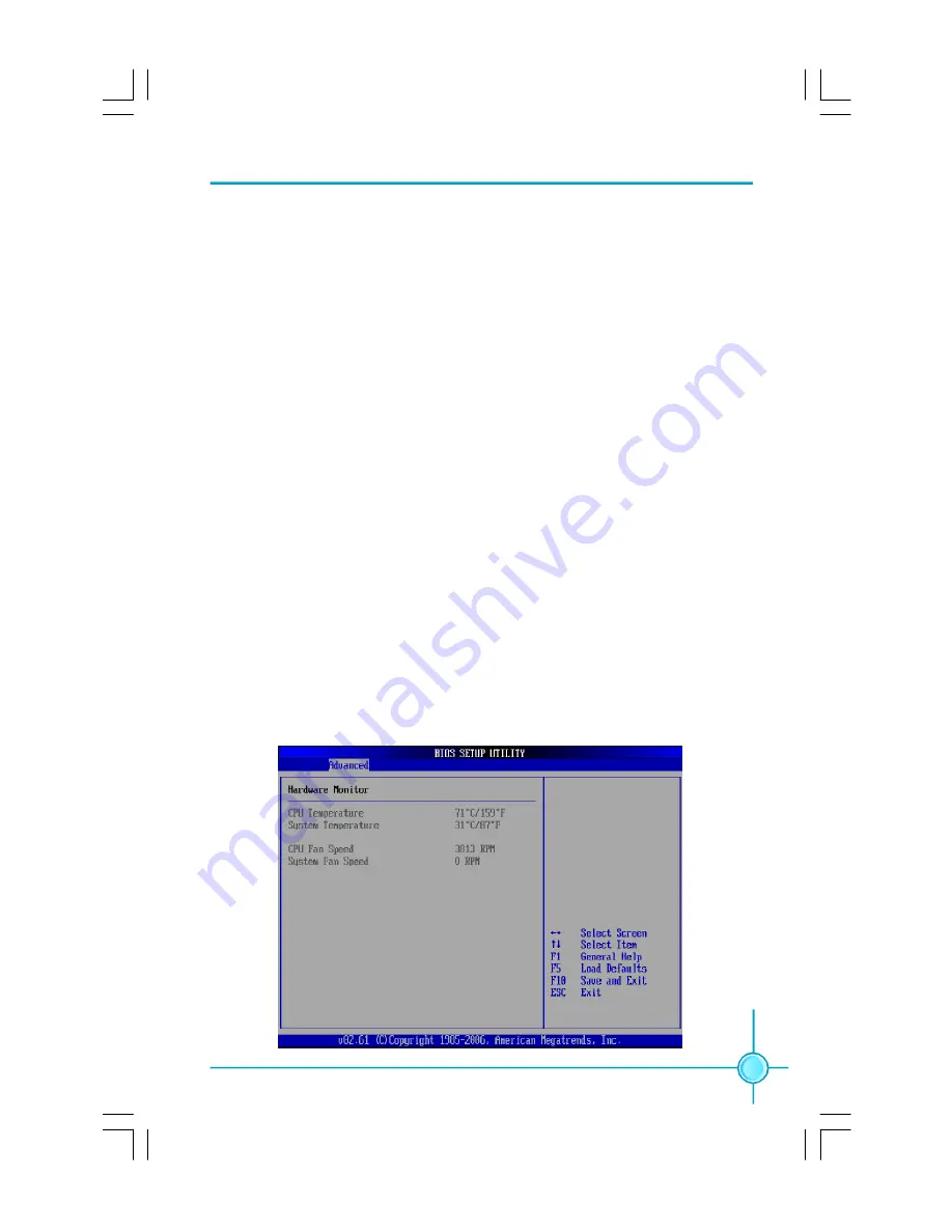
Hardware Monitor

Press< Enter> to display CPU/System temperature and CPU/System Fan

    Speed. They will be automatically detected by the system.

Hardware Monitor

PDF 

文件使用

 "pdfFactory" 

试用版本创建


Æ


Æ


www.fineprint.com.cn

Summary of Contents for 945GZ7MC

Page 1: ...to avoid such problems Warning means that a potential risk of property damage or physical injury exists More information If you want more information about our products please visit Foxconn s website http www foxconnchannel com WEEE The use of the symbol indicates that this product may not be treated as household waste By Ensuring this product is disposed of correctly you will help prevent potenti...

Page 2: ...haracteristics of information technology equipment þ EN 61000 3 2 2000 Electromagnetic compatibility EMC Part 3 Limits Section 2 Limits for harmonic current emissions equipment input current 16A per phase þ EN 61000 3 3 A1 2001 Electromagnetic compatibility EMC Part 3 Limits Section 2 Limits of voltage fluctuations and flicker in low voltage supply systems for equipment with rated current 16A þ EN...

Page 3: ...cturer HON HAI PRECISION INDUSTRY COMPANY LTD Address 66 CHUNG SHAN RD TU CHENG INDUSTRIAL DISTRICT TAIPEI HSIEN TAIWAN R O C SupplementaryInformation This device complies with Part 15 of the FCC Rules Operation is subject to the follow ing two conditions 1 this device may not cause harmful interference and 2 this device must accept any interference received including interference that may cause u...

Page 4: ...nstallation Instructions CPU 6 Memory 9 Power Supply 10 Other Connectors 11 Expansion Slots 13 Jumpers 14 BIOS Description Enter BIOS Setup 16 Main menu 16 Advanced Menu 18 Power Menu 20 Boot Menu 21 Exit Menu 22 Table of Contents Chapter 3 3 Chapter 2 2 Chapter 1 1 ...

Page 5: ...ure to switch off the DC power supply may result in serious damage to your system or memory module Attention We cannot guarantee that your system will operate normally while over clocked Normal operation depends on the over clock capacity of your device Attention Attention Since BIOS programs are upgraded from time to time the BIOS description in this manual is just for reference We do not guarant...

Page 6: ...Default is omitted K with onboard Gigabit LAN S with SATA function 2 with DDR2 Slots H comply with RoHS directive You can find PPID label on the motherboard It indicates the functions that the motherboard has For example The latters on the black mark of the PPID label mean that the motherboard supports 6 channel Audio 6 Default is omitted onboard 10 100M LAN L Default is omitted SATA function S DD...

Page 7: ...perior performance reliability and quality at a reasonable price This motherboard adopts the advanced Intel 945GZ ICH7 chipset providing users a computer platform with a high integration compatibility performance price ratio This chapter includes the following information v Main Features v Layout v Rear I O Ports 1 1 ...

Page 8: ...o 240 pin DIMM slots Supports dual channel DDR2 533 400 Memory Supports up to 4GB DDR2 memory USB 2 0 Ports Supports hot plug Six USB 2 0 ports Two rear panel ports two onboard USB headers providing four extra ports Supports USB 2 0 protocol up to 480Mb s transmission rate Onboard Serial ATA II 300MB s data transfer rate Supports up to two serial ATA II devices Onboard Graphics Supports integrated...

Page 9: ...3 Chapter 1 Product Introduction Layout Note The above motherboard layout is provided for reference only please refer to the physical motherboard Expansion Slots Two PCI slots One PCI Express x1 slot ...

Page 10: ...one jack When using a 2 channel sound source the Line out jack is used to connect to speaker or headphone The Line in port connects to an external CD player tape player or other audio device The Microphone jack is used to connect to the microphone When using a 6 channel sound source connect the front speaker to the green audio output Connect the rear speaker to the blue audio output Connect the ce...

Page 11: ...d pin headers and the mounting of jumpers Caution should be exercised during the installation of these modules Please refer to the motherboard layout prior to any installation and read the contents in this chapter carefully This chapter includes the following information v CPU v Memory v Power supply v Other Connectors v Expansion Slots v Jumpers Chapter2 2 ...

Page 12: ...ort list on this motherboard please visit the website http www foxconnchannel com Installation of CPU Below is the CPU socket illustration Follow these procedures to install a CPU Load lever Load plate Protective cover 1 Use thumb and forefinger to hold the hook of the load lever and pull the lever down and away from socket to unlock it Lift the load lever 2 Push down the rear tab with your forefi...

Page 13: ...ovides the orientation directed function Lower the CPU straight down without tilting or sliding the CPU in the socket 4 After installing the CPU remove the protective cover from load plate The protective cover is used to protect the contacts of the socket Do not discard the protective cover Always replace the socket cover if the CPU is removed from the socket Alignment Key SocketCutouts Pin 1 posi...

Page 14: ...ad plate then the CPU is locked completely Warning Excessive temperatures will severely damage the CPU and system Therefore you should install CPU cooling fan and make sure that the cooling fan works normally at all times in order to prevent overheating and damaging to the CPU Please refer to your CPU fan user guide to install it properly ...

Page 15: ... the center of the DIMM slot and the memory module can be fixed in one direction only Unlock a DIMM slot by pressing the module clips outward 2 Align the memory module to the DIMM slot and insert the module vertically into the DIMM slot 3 The plastic clips at both sides of the DIMM slot will lock automatically 128 针 112 针 Warning Be sure to unplug the AC power supply before adding or removing expa...

Page 16: ...nector on the motherboard Firmly plug the power supply cable into the connector and make sure it is secure 4 pin ATX_12 V Power Connector PWR2 The 4 pin ATX 12V power supply connect to PWR2 and provides power to the CPU 12V 12V 3 1 PWR2 4 2 GND GND 20 Pin Power supply 24 Pin Power supply Note We recommend you use 24 pin ATX power supply If you want to use 20 pin power supply you need to align the ...

Page 17: ...AN CPU_FAN The fan speed can be detected and viewed in PC Health Status section of the CMOS Setup These fans will be automatically turned off after the system enters S3 S4 and S5 mode SYS_FAN 1 SENSE 12V GND CPU_FAN POWER GND 1 CONTROL SENSE USB Headers F_USB1 F_USB2 In addition to the two USB ports on the rear panel this series of motherboards also have two 10 pin headers on board which may be us...

Page 18: ... S4 S5 status the LED is off Power Switch Connector PWRSW Attach the connector to the power button of the case Pushing this switch allows the system to be turned on and off rather than using the power supply button Audio Connector F_AUDIO The audio connector supports HD audio standard It provides two kinds of audio output choices the Front Audio and the Rear Audio Front Audio supports re tasking f...

Page 19: ... such as a LAN card USB card SCSI card and other cards that comply with PCI specifications PCI Express x1 Slot This motherboard has one PCI Express x1 slot that designed to accommodate less bandwidth intensive cards such as a modem or LAN card 3 3V_DVDD_CORE HDA_DH SDI SDO BCLK RST GND 3D3V_SYS SYNC GND 12V 1 2 15 16 RSVD RSVD RSVD KEY 3D3V_DUAL GND HDAudio DigitalConnector HDA_DH The connector is...

Page 20: ...board uses the CMOS RAM to store all the set parameters The CMOS can be cleared by removing the CMOS jumper Warning 1 Disconnect the power cable before adjusting the jumper settings 2 Do not clear the CMOS while the system is turned on NORMAL Default CLR_CMOS CLEAR 1 1 Jumper Diagram Definition Description 1 2 Set pin1 and pin2 closed 2 3 Set pin2 and pin3 closed Closed Set the pin closed Open Set...

Page 21: ...eters are also provided You have to run the Setup Utility when the following cases occur 1 An error message appears on the screen during the system POST process 2 You want to change the default CMOS settings This chapter includes the following information v Enter BIOS Setup v Main Menu v Advanced Menu v Power Menu v Boot Menu v Exit Menu Chapter3 3 ...

Page 22: ... Utility ESC Boot Menu F1 Setup F10 System Recovery Note We do not suggest that you change the default parameters in the BIOS Setup and we shall not be responsible for any damage that result from any changes you make Main Menu This main menu is used to set up the standard CMOS features such as the system date system time HDD model and so on Use the arrow keys select the item to set up and then use...

Page 23: ...ppy Diskette A Sets the type of floppy drive installed v1st 2nd 3rd 4th Drive While entering setup the BIOS automatically detects the presence of drives There is a separate sub menu for each device Enter the information directly from the keyboard and press Enter vInstalled Memory The option identifies the capacity of memory installed in the system vMemory Bank 1 2 This item show Not Installed if n...

Page 24: ...S 2 mouse Select Enabled to enable and support PS 2 mouse function Select Disabled to disable the PS 2 mouse function and free up IRQ12 vOnboard PATA SATA Adapters Press Enter to set enable or disable onboard PATA SATA controller vUSB Legacy Mode Support Enables support for Legacy Universal serial Bus vOnboard LAN The option is used to enable or disable Onboard LAN function vOnboard LAN Boot ROM T...

Page 25: ...can not be modified using the user password When you select the Supervisor User Password option the following message will appear in the center of the screen which will help you to set the password Enter Password Enter your password not exceeding 8 characters then press Enter The password you entered will replace any previous password When prompted key in the new password and press Enter vChange S...

Page 26: ...the power button is pressed Power On restores power as soon as AC is applied vWOL Wake On LAN in S4 The option is used to enable or disable the Wake On LAN support for the S4 state vHyper Threading Technology This option is used to turn on or off the Hyper Threading function of the CPU Note This function will not be displayed until a CPU that supports Hyper Threading has been installed ...

Page 27: ... 21 vBoot time Diagnostic Screen The option is used to display the diagnostic screen during boot vBoot Device Priority Press Enter to select the search order for the types of boot devices Boot Menu Boot Menu Boot Device Priority ...

Page 28: ...p and hard drives group and network group installed in the system Press Enter to go to the sub menu then use the up or down arrow to select the device then or to move the device upward or downward Exit Menu Exit Menu vExit Saving Changes Once you finished making your selections choose this option from the Exit menu to ensure the values you selected are saved to the CMOS RAM vExit Discarding Change...

Page 29: ...3 BIOS Description 23 vDiscard Changes This option allows you to discard the selections you made and load previous values from CMOS for all setup items vSave Changes Select YES to save changes to CMOS and exit ...

Reviews: