background image

30

Chapter 3   BIOS Description

BIOS Features

v

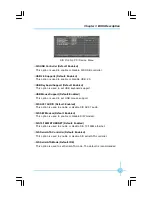
[SuperBoot] SuperBoot (Default: Disabled)

SuperBoot allows system-relevant information to be stored in CMOS upon
the first normal startup of your PC,  and the  relevant parameters will be
restored to help the system start up more quickly on each subsequent startup.
The available setting values are: Disabled and Enabled.

v

[SuperBIOS-Protect] SuperBIOS-Protect (Default: Disabled)

Super-BIOS Protect funtion protects your PC from being affected by viruses,

   e.g. CIH. The available setting values are: Disabled and Enabled.

v

[SuperRecovery] SuperRecovery Hotkey (Default: F12)

SuperRecovery provides the users with an excellent data protection and
HDD recovery function. There are 12 optional settings, and the default
setting is F12.

v

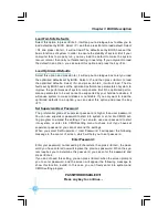
[SuperSpeed] CPU Clock (default: Depending on CPU)

The conventional over-clock method uses the jumpers on the motherboard,
and it is both troublesome and apt to errors. By using SuperSpeed, a CPU

can be overclocked by keying in the desired in the CPU clock range.

BIOS Features Menu

Warning:

Be sure your selection is right. CPU overclock will be dangerous!

W e will not be responsible for any damage caused.

PDF created with pdfFactory Pro trial version 

www.pdffactory.com

Summary of Contents for 760GXK8MB series

Page 1: ...in English for 760GXK8MB series motherboard P N 91 181 W76 G0 0E Symbol description Note refers to important information that can help you to use motherboard better Attention indicates that it may da...

Page 2: ...aracteristics of information technology equipment EN 61000 3 2 2000 Electromagnetic compatibility EMC Part 3 Limits Section 2 Limits for harmonic current emissions equipment input current 16A per phas...

Page 3: ...cturer HON HAIPRECISION INDUSTRY COMPANYLTD Address 66 CHUNG SHAN RD TU CHENG INDUSTRIAL DISTRICT TAIPEI HSIEN TAIWAN R O C Supplementary Information This device complies with Part 15 of the FCC Rules...

Page 4: ...s 27 BIOS Features 30 Advanced BIOS Features 31 Advanced Chipset Features 32 Integrated Peripherals 33 Power Management Setup 37 PnP PCIConfigurations 39 PC Health Status 40 Frequency Voltage Control...

Page 5: ...ilure to switch off the DC power supply may result in serious damage to your system or memory module Warning We cannot guarantee that your system will operate normally while over clocked Normal operat...

Page 6: ...fers superior performance reliability and quality at a reasonable price This motherboard adopts the advanced SiS 760GX SiS964 964L chipset providing us ers a computer platform with a high integration...

Page 7: ...up to 2GB USB 2 0 Ports l Supports hot plug l Eight USB 2 0 ports four rear panel ports two onboard USB headers providing four extra ports l Supports wake up from S1 and S3 mode l Supports USB 2 0 pro...

Page 8: ...V3 5 Compliant l Supports AGP 8X 4X Interface w Fast Write Transaction BIOS l Licensed advanced AWARD Phoenix BIOS supports flash ROM Plug and Play l Supports IDE HDD CD ROM SCSI HDD or USB device bo...

Page 9: ...ipset 9 Clear CMOS Jumper 10 Speaker Connector 11 Front Panel Connector 12 SATA Connectors optional 13 System Fan Connector 14 IDE Connector 15 CPU Fan Connector 16 FDD Connector 17 ATX 12V Power Conn...

Page 10: ...n of hard drive and floppy drive data cables and setting up various other feature of the motherboard Caution should be exercised during the in stallation process Please refer to the motherboard layout...

Page 11: ...socket Carefully insert the CPU into the socket until it fits in place 3 When the CPU is in place press it firmly on the socket while you push down the socket lever to secure the CPU The lever clicks...

Page 12: ...nism base surrounds the CPU socket Installation of CPU Fan New technology allows processors to run at higher and higher frequencies To avoid problems arising from high speed operation for example over...

Page 13: ...an to module base 6 Connect the fan s power cable to the appropriate 3 pin terminal on the motherboard 4 Align the other end of the reten tion bracket to fasten the cooling set on the top of the reten...

Page 14: ...this motherboard Package 754 Pin Lidded O PGA 754 Pin Lidded O PGA 754 Pin Lidded O PGA 754 Pin Lidded O PGA 754 Pin Lidded O PGA 754 Pin Lidded O PGA 754 Pin Lidded O PGA Cache Size 512 KB 512 KB 1...

Page 15: ...stallation of DDR Memory 1 There is only one gap in the center of the DIMM slot and the memory module can be fixed in one direction only 2 Align the memory module to the DIMM slot and insert the modul...

Page 16: ...Samsung PC2100 DDR266 256 MB Kingmax PC2100 DDR266 256 MB Nanya PC2100 DDR266 512 MB Hynix PC2100 DDR266 256 MB Kingston PC2100 DDR266 512 MB RamBo PC2700 DDR333 256 MB Ramaxel PC2700 DDR333 256 MB T...

Page 17: ...Power Button option in the BIOS Power Management Setup ATX Power Connector PWR1 PWR1 is the ATX power supply connector Make sure that the power supply cable and pins are properly aligned with the conn...

Page 18: ...pointing devices or other serial devices VGA Connector The VGA connector is for output to VGA compatible device Parallel Port Printer Port The 25 pin port connects a parallel printer a scanner or othe...

Page 19: ...ed to connect to speaker or headphone the Line in port connects to an external CD player tape player or other audio devices The MIC is used to connect to microphone When using a 6 channel sound source...

Page 20: ...bon cable Connect the cable s blue connector to the primary recommended or secondary IDE connector then connect the gray connector to the Ultra DMA133 100 66 slave device hard disk drive and the black...

Page 21: ...ont panel of the case The Power LED indicates the system s status When the system is in S0 status the LED is on When the system is in S1 status the LED is blink When the system is in S3 S4 S5 status t...

Page 22: ...VCC D5 D5 Empty GND NC VCC GND D4 1 2 9 10 D6 VCC D7 D7 Empty GND NC VCC GND D6 1 2 9 10 Fan Connectors CPU_FAN FAN1 There are two fan headers on this motherboard These fans will be automati cally tu...

Page 23: ...A and a LAN adapter which supports this function Then connect the header to the relevant connector on the LAN adapter set MACPME Power Up Control to Enabled in the Power Management Setup section of th...

Page 24: ...ont Audio then the Line out Rear Audio on the rear panel will not work If you do not want to use the Front Audio pin 5 and 6 pin 9 and 10 must be short and then the signal will be sent to the rear aud...

Page 25: ...t supports 1 5V AGP cards AGP is an interfacing specification designed to display 3D images It provides a specialized 66MHz 32 bit channel to allow the graphic controller to directly access the master...

Page 26: ...cards listed above Other AGP cards manufactured by other ven dors may not be suitable for this motherboard Vendor Type Vedio Memory GeForce2 GeForce2 MX 400 32 MB LeadTek LeadTek S650 128 MB GA GF GA...

Page 27: ...any jumper settings Description of Jumpers 1 For the jumpers on this motherboard pin 1 can be identified by the silk screen printed next to it However in this manual pin 1 is simply labeled as 1 2 Th...

Page 28: ...3 Turn the AC power supply back on Warning 1 Disconnect the power cable before adjusting the jumper settings 2 Do not clear the CMOS while the system is turned on 1 2 3 1 2 3 Normal default Clear CMO...

Page 29: ...the system POST process 2 You want to change the default CMOS settings This chapter includes the following information v Enter BIOS Setup v Main Menu v Standard CMOS Features v BIOS Features v Advance...

Page 30: ...creen DEL to enter SETUP Main Menu The main menu allows you to select from the list of setup functions and two exit choices Use the arrow keys to select among the items and press Enter to accept or go...

Page 31: ...PCI settings and parameters can be modified through this menu PC Health Status This will display the current status of your PC Frequency Voltage Control Frequency and voltage settings can be adjusted...

Page 32: ...is option allows you to set up the desired time usually as the current time with hour minute second format IDE Channel 0 1 Master Slave Channel 2 3 Master These categories identify the HDD types of 4...

Page 33: ...40 Color Graphic Adapter powering up in 40 column mode CGA 80 Color Graphic Adapter powering up in 80 column mode MONO Monochrome adapter including high resolution monochrome adapters Halt On This ca...

Page 34: ...ned by POST Power On Self Test of the BIOS Base Memory The BIOS POST will detemine the amount of base or conventional memory installed in the system Extended Memory The BIOS determines how much extend...

Page 35: ...uses e g CIH The available setting values are Disabled and Enabled v SuperRecovery SuperRecovery Hotkey Default LSHIFT F12 SuperRecovery provides the users with an excellent data protection and HDD re...

Page 36: ...and Enabled Note Such function provides protection to the startup sector only it does not protect the entire hard disk vQuick Power On Self Test Default Enabled With this function enabled the system w...

Page 37: ...nter to set the items about OnChip VGA Control vMemory Hole at 15M 16M Default Disabled This option is used to determine whether the 15M 16M address field of memory is reserved for the ISA expansion c...

Page 38: ...r to set onchip PCI device Please refer to page 35 vOnboard SuperIO Device Press enter to set onchip onboard SuperIO device Please refer to page 36 vOnboard Lan Boot ROM Default Disabled This option i...

Page 39: ...to detect which PIO mode is the best or select a PIO mode from 0 4 vPrimary Secondary Master Slave UItraDMA Default Auto UItraDMA technology provides faster access to IDE devices If you install a devi...

Page 40: ...is used to set USB mouse support vSIS AC97 AUDIO Default Enabled This option is used to enable or disable SIS AC97 audio vSIS S W Modem Default Enabled This option is used to enable or disable S W mod...

Page 41: ...s determined by the infrared module installed on the board vUR2 Duplex Mode Default Half This option is available when UART 2 mode is set to either ASKIR or IRDA This option enables you to determine t...

Page 42: ...e the power will not shut off and the supply status will remain as it is in S1 mode the computer can beresumed at any time When you select S3 STR mode the power will be cut off after a delay period Th...

Page 43: ...the modem receives an incoming call vPM Wake Up Events Press enter to set the items of PM Wake Up Events vAMD K8 Cool n Quiet Control Default Auto When this item is set as Auto AMD Cool n Quiet techno...

Page 44: ...y distribute interruption resources If the ISA cards you installed not supporting PnP you will need to select Manual and manually adjust interruption re sources in the event of hardware conflicts Howe...

Page 45: ...tatus vShutdown Temperature Default Disabled This option is used to set the system temperature upper limit When the temperature exceeds the setting value the motherboard will automatically cut off pow...

Page 46: ...uce electromagnetic interference vAsync SRC ZCLK AGP PCI Default Disabled Enabling this item can fix the SRC ZCLK AGP PCI in a safe value to ensure the PCI SATA device stability when CPU overclocks vS...

Page 47: ...by your hardware devices it will cause system to make mistakes or not stable If you only want to load the optimized defaults in an option you can select this option and press the key F7 Set Superviso...

Page 48: ...center of screen Quit Without Saving Y N Y At this time press Y to exit CMOS but it does not save your amendment in CMOS press N ESC to return main menu Under the menu Advanced BIOS Features Setup if...

Page 49: ...CD that comes with the motherboard contains useful software and several utility drivers that enhance the mother board features This chapter includes the following information v Utility CD content v S...

Page 50: ...ies Use this option to install additional software programs A SuperUtility a SuperStep Superstep is powerful and easy to operate tool for overclocking You can quickly increase your CPU s working frequ...

Page 51: ...46 Chapter 4 Driver CD Introduction Start to install drivers Select Install Driver to enter the driver installation menu as following pic Click the relevant button to install the Drivers Click here...

Reviews: