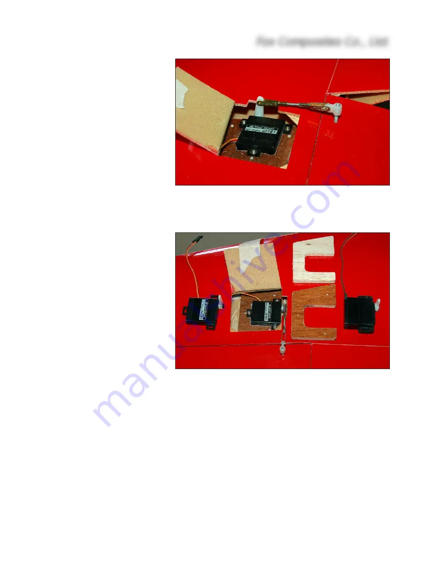
the wing root, in line with the
air-flow during flight. This only
a few degrees off the ‘ideal’ 90°
to the hinge line of the ailerons,
and is close enough that there
is no noticeable binding or lost
movement. If you want to add
‘scale’ linkage covers later you
will need the linkages at this
angle, and not at 90 degrees to
the aileron leading edge.
File or sand the 5mm x 20mm
notches on the inner edges of
the servo hatches, as shown,
for the servo arms to exit the
wing. Carefully sand the inside
surface of the wing skin and
back of the wing spar where
the mounts will be glued for a
good bond, and clean off the
dust. Glue the mounts into the
wing using a little 30 minute
epoxy and micro-balloons mix-
ture. When cured, remove the
servos and apply a fillet of glue
all around the mounts, also
making sure that they are firmly
glued to the back of the spar.
Tape the ailerons in the neutral
position. Carefully mark the line
(on masking tape) of the link-
age, exactly in line with the
servo arms and perpendicular
to the wing root. The control horns are made from the 35mm lengths of M3 threaded rod included
in the hardware. Insert the small plywood reinforcing strips (6 x 15 x 30mm) into the inboard ends
of the ailerons, in line with the linkage, and glue in place to the aileron leading edge and lower skin
with a
little
30 minute epoxy and micro mixture.
Drill right thru' the aileron on the marked line, exactly 10mm behind the front edge of the aileron,
using a sharp Ø 2.2 or 2.3mm drill. Use a 90° square to keep the drill perpendicular to the bottom
surface of the elevators. The holes should be just behind, or against, the balsa elevator spars,
and must pass thru’ the ply reinforcing strips. Now thread these holes, right thru' the ailerons, using
an M3 tap. Sand both ends of the threaded rod flat, and screw on the plastic adapter provided.
Screw it into the tapped hole until the upper end is flush with the top surface of the aileron. The
M3 rod must now be secured in place, by applying glue through the open (root) end of the aileron.
Apply one drop of thick CA and, when cured, add some 30 minute epoxy and micro-balloons mix-
ture to fill the space between the ply reinforcing strips and upper skin.
Make up the linkages between the servos and aileron horns using M2, M2.5 or 2 x 56 UNC cle-
vises and threaded rods. The linkages will need to be approx. 55mm long, clevise pin-to-pin. Fit
Fox Composites Co., Ltd.
8
(above) Completed aileron servo, linkage and horn.
(below) We advise you to use ‘wing-mount’ servos with in-
tegral mounting tabs, like the digital JR DS-161 and DS-
3301/3328 servos shown here.


