


Owner’s Manual
05/00
Section H
Page 5
spaces.
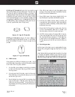
Orient the boat for maximum dissipation of the exhaust
or DO NOT run the boat or boat equipment for extended
periods under these conditions. See Figure H1.
Figure H1: The effect of sea walls and other confined
A boat operator should be aware that carbon monoxide
is emitted from any boat’s exhaust. The operation, moor-
ing, and anchoring in an area containing other boats
may be in an atmosphere containing CO not of the
operator’s making. An operator likewise needs to be
aware of the effect of his actions on other boats. Of
prime concern is the operation of an auxiliary generator
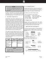
with boats moored along side each other. Be aware of
the effect your exhaust may have on other vessels and
be aware that the operation of other vessel’s equipment
may affect the carbon monoxide concentration on your
vessel. See Figure H2.
Figure H2: The effect of boats moored along side.
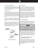
K. Backdrafting (Station Wagon Effect)
Backdrafting or the “station wagon effect” is caused by
air movement over or around a boat creating a low pres-
sure area of suction area around the stern which can
increase CO level on the boat. Backdrafting can be
affected by relative wind direction , boat speed, and boat
trim angle. See Figure H3 Backdrafting - Airflows Over
Boat and Behind Transom”.
Under certain speed and operating conditions the low
pressure area may form in other regions and permit car-
bon monoxide to enter the hull through openings that
are not on the back of the vessel. Boat factors which
may affect CO concentration:
Figure H3: Backdrafting - Air flows over boat and
behind transom.
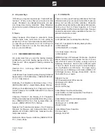
1.
Inefficient trim angle. See Figure H4.
2.
Excessive or unequally distributed weight.
Figure H4: Inefficient trim angles.
3.
Canvas Configurations - Under various conditions,
adding or removing canvas may raise or lower CO
levels. See Figures H3, H4 & H6.
Exhaust Fumes!
Hull exhaust from your boat can cause exces-
sive accumulation of poisonous carbon mon-
oxide gas within cockpit areas when using pro-
tective weather coverings (while underway or
while stationary). Provide adequate ventilation
when the canvas top, side curtains and/or back
(aft) curtains are in their closed protective posi-
tions.
Summary of Contents for Horizon 200
Page 1: ......
Page 56: ...Owner s Manual 05 00 Section G Page 6 Figure G7 General Water System Diagram WATER SYSTEM ...
Page 80: ...Owner s Manual 05 00 Section J Page 15 Figure J16 Skiing Signals ...
Page 131: ...Owner s Manual 05 00 Fuel Log Page 1 FUEL LOG DATE HOURS RUN FUEL GAL RANGE MILES RPM MPH GPH ...
Page 132: ...Owner s Manual 05 00 Fuel Log Page 2 FUEL LOG DATE HOURS RUN FUEL GAL RANGE MILES RPM MPH GPH ...
Page 133: ...Owner s Manual 05 00 Fuel Log Page 3 FUEL LOG DATE HOURS RUN FUEL GAL RANGE MILES RPM MPH GPH ...
Page 134: ...Owner s Manual 05 00 Service Log Page 1 SERVICE LOG DATE HOURS MAINTENANCE PERFORMED ...
Page 135: ...Owner s Manual 05 00 Service Log Page 2 SERVICE LOG DATE HOURS MAINTENANCE PERFORMED ...
Page 136: ...Owner s Manual 05 00 Service Log Page 3 SERVICE LOG DATE HOURS MAINTENANCE PERFORMED ...
Page 138: ...Page 1 1998 1999 MODEL YEAR 200 HORIZON 245 SUNDOWNER Electrical Schematics ...
Page 140: ......


