background image

AAØZZ EZKeyer III   23 November 2014 

- 7 - 

Copyright 2014 AAØZZ


___ Install the 10k potentiometer, R1 in the shims.  Insert the 4 signal pins and two side mounting 
pins into the shim stack.  It sometimes helps to insert the four pot pins first and rotate back on the 
two mounting pins.  Putting pressure from the side of these pins with a small screwdriver helps 
them to seat properly in the holes. 

Make sure the shim corner wire connections do not make 

contact with the frame of the pot.  If one does does, remove the pot and trim the wire/solder 
connection and reinstall the pot.

  Make sure it is fully seated.  Solder all four pins as they enter 

the shim.  Then solder the two mounting pins into their holes in the shim. 
 
___ Install the 10k trimmer potentiometer, R2.  Make sure it is fully seated before soldering.   Turn 
fully clockwise for maximum volume.  Adjust to a comfortable level later. 
 
___ Install the three pushbuttons.  Mount them all the way down on the PC board as far as they go.  
Solder one switch and align it vertically by sight.  If adjustments are needed, fix it by heating one 
pin at a time and gradually moving it into position.  Similarly, mount and align the other two 
pushbuttons.  Looking from the side the three pushbuttons should be aligned.  
 
___ Install the PIC in the socket. Orient the notch per the silk-screen on board and the notch in the 
socket. To prepare the PIC for installation, hold it by the two ends, turn it on its and side, press 
down on a table top so all 9 pins on that side are bent in a bit - until they are pointing straight down. 
Turn the PIC over and do the same with the other 9 pins. Now both sets of pins should be aligned 
so it will insert easily into the socket. 


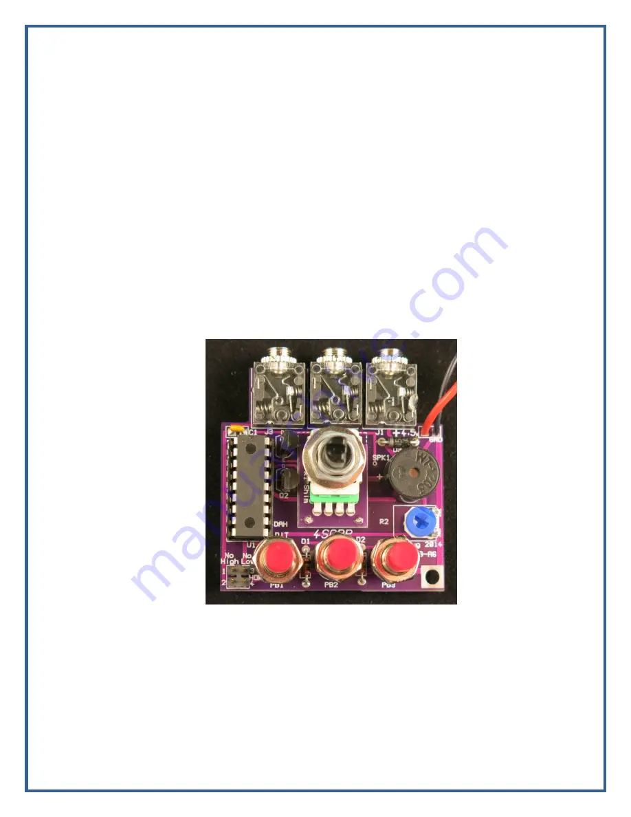
Figure 4.8 – Completed Board  


___ Consider whether or not you want to use the speed-limit jumpers (HDR1).  See the Speed 
Limits description in Section 7.4.  You can always change it later, of course, but it's easier to do 
before you install the board in the case. 
 
___ Set the trimmer pot, R2, to desired speaker volume setting.  As a starting point, turn it to 
maximum volume (clockwise).  If you are using the onboard piezo you will probably like it in the 
maximum volume position.  If you are using one of the external speakers you may want to turn it 
back a bit after testing in the case.   
 
Figure 4.8 shows the completed PC Board. 

Summary of Contents for EZKeyer III

Page 1: ...stalling a larger speaker 15 7 3 Installing a Knob on the Speed Pot 16 7 4 Quick test before using 16 7 5 Getting familiar with the EZKeyer III 16 8 EZKeyer III Commands 18 Appendix A Mute Timing Diagram 20 Appendix B EZKeyer III PC Board Schematic 22 Appendix C EZKeyer III PC Board Parts Placement 23 Appendix D EZKeyer III Parts List 24 1 Introduction This full featured PIC based iambic Morse cod...

Page 2: ...lation straight key cootie key modes Sequenced receiver mute line low active for 7ms before and after keying the transmitter Speed and modes saved in non volatile memory EEPROM Speed entered by command or changed on the fly via the paddles Tune mode Current speed reported by command 600 Hz sidetone may be turned off Autospacing between elements of characters optional Paddle Dash Dot swap command C...

Page 3: ...acers 6 32 threads ___ 8 6 32 x 3 8 screws ___ 2 pin header shunts ___ 1 knob 1 2 diameter 1 4 shaft ___ 1 Battery holder 3xAA 4 Building the PC Board This is the bare PC board Figure 4 1 Bare Board ___ Break off the two shims Figure 4 2 Figure 4 2 Board with Shims Removed ...

Page 4: ...ugh the same corner of the second shim and finally through the corresponding hole in the PC board Look at the picture in Figure 4 5 and make sure you have it in the correct location The four holes are toward the bottom of the shims and the rectangular cutout on the PCB is also on the bottom Figure 4 4 Wire in One Corner ___ Once again make sure you have the shims as shown in Figure 4 4 Make sure t...

Page 5: ...he board should look like Figure 4 5 Figure 4 5 Wires in Four Corners ___ Turn board over and solder all four wires coming through the corner holes Fig 4 6 Trim Figure 4 6 Four Corner Wires on Back Side ___ Turn board back to front side and solder all four wires coming through the corner holes Fig 4 7 Trim the wire solder connections close to the board It s important to make sure the solder point ...

Page 6: ... for the other two jacks ___ Install capacitor C1 located just above the 18 pin DIP socket Solder ___ Locate and identify diodes D1 D2 and D3 Notice the differences D1 and D2 are the small glass diodes 1N4148 while D3 is the black body diode 1N5817 with white markings ___ Install diodes D1 and D2 1N4148 the small glass diodes Make sure the banded ends of the diodes are installed per the silk scree...

Page 7: ...ded fix it by heating one pin at a time and gradually moving it into position Similarly mount and align the other two pushbuttons Looking from the side the three pushbuttons should be aligned ___ Install the PIC in the socket Orient the notch per the silk screen on board and the notch in the socket To prepare the PIC for installation hold it by the two ends turn it on its and side press down on a ...

Page 8: ... Approach 1 Assemble the case without soldering Hold in place with tape on the corners or with a few rubber bands around it Solder all four edges and four corners Approach 2 Assemble and tack solder one edge at a time After all four edges are tacked on and aligned add additional solder tack points Solder all four corners Here is what the case looks like at first Figure 5 1 Case Outside Figure 5 2 ...

Page 9: ...k and forth over the sandpaper Be very careful not to sand any of the soldermask surfaces Figure 5 4 Mill File Method 1 ___ Assemble the case four edge pieces and the bottom and hold it together with tape on the four corners Figure 5 5a or alternatively you could secure it with several rubber bands Figure 5 5b Make sure the end piece with the three holes is at the top side of the box so you can re...

Page 10: ...along the entire edges but it is not necessary You may find it easier to do this by standing the box upright on an edge with the corner to be soldered on the bottom ___ Install the four 1 75 spacers in the inside corners of the case For each spacer use a 3 8 screw through a rubber bumper and then through the case bottom and into the spacer See Figure 5 9 Method 2 ___ Place a small solder blob in t...

Page 11: ... 7 First Side Attached ___ In a similar manner tack the other side to the bottom board See Figure 5 8 Figure 5 8 Second Side Attached ___ Now tack the Top end piece to the bottom board See Figure 5 9 Be careful to use the correct end piece for each end Look at the silk screened commands on the other side of the bottom board and make sure the end piece with the three holes is on the top side as you...

Page 12: ...10 Figure 5 10 All Sides ___ When all edges are tacked in place and all fit properly add additional solder to various places along the edges Figure 5 11 You don t have to solder the entire edges but there is no harm if you want to Figure 5 11 Extra Solder Along Bottom Edges ___ In a similar manner solder the vertical edges of the four corners Figure 5 12 ...

Page 13: ... rubber bumper and then through the case bottom and into the spacer See Figure 5 13 Figure 5 13 Corner Spacers 6 Installing the PC Board in the Case ___ Install three AA batteries in a battery pack See Section 7 1 for example sources and part numbers ___ Attach the 3 cell AA battery pack to the PCB See Figure 4 8 Solder the red wire to the terminal and the black wire to the other terminal WATCH TH...

Page 14: ...he case Attach with the three nuts Be careful not to scratch the case as you tighten the nuts Figure 6 1 Board Mounted in Case ___ Place the top cover over the three pushbuttons and speed pot Figure 6 2 ___ Install the speed pot and pushbutton washers and nuts to hold the top cover on but leave loose ___ Attach the cover with 3 8 screws into the four corner spacers Tighten ___ Tighten the speed po...

Page 15: ...er One common inexpensive speaker that has been tested with good results is Radio Shack part number 273 073 For maximum volume the case has specifically been designed to accommodate piezo part number 102 2200 ND from Digikey This piezo is shown in Figure 7 1 If you chose to use an external speaker remove the on board speaker first and attach the wires for the external speaker to these holes in the...

Page 16: ...he speed pot if it is active and send some code to get the feel of the keyer and the default settings The iambic routines are smooth with a good feel and entering commands quickly becomes second nature Go through the command list entering each command This will familiarize you with the procedure and features and it only takes a few minutes Note Holding pushbutton 1 down while powering up will caus...

Page 17: ...all the way clockwise is 32 WPM Similarly if you know you never want to use the slowest speeds of the EZKeyer down to 5 WPM you can put a shunt jumper between pins 3 and 4 of HDR1 Now the lowest speed spot settings of the pot are removed so that the lowest speed with the pot is turned all the way counter clockwise is 15 WPM If you place both jumpers on HDR1 the speed will vary from 15 to 32 wpm wh...

Page 18: ... release the button and you re at the new speed This change isn t stored in EEPROM but will remain in use until you power down i e remove the battery 8 EZKeyer III Commands In addition to asking for a message to be played pushbutton 1 is also used to send commands to the keyer If it is pressed and released quickly it sends Message 1 If it is pressed and held for about 2 seconds before releasing th...

Page 19: ...CW speed between 5 and 55 WPM Default is 15 WPM Keyer response is a DIT requesting the first digit followed by another DIT requesting the second digit A T may be entered instead of a zero Response is a if the input is invalid Quick speed changes can be done without using the S command Simply press and hold the command pushbutton pushbutton 1 and then tapping the left usually DIT paddle or the righ...

Page 20: ...he end of the message with a period Response after the period or maximum characters is R 3 Load User Message 3 Same as 1 except maximum message size is 95 characters Indicate the end of the message with a period Response after the period or maximum characters is R Appendix A Mute Timing Diagram The ideal DIT to Space ratio is always 1 0 The ideal DAH to Space ratio is always 3 0 With Mute on as sh...

Page 21: ...ber 2014 21 Copyright 2014 AAØZZ Similarly At 5 WPM the DIT to Space ratio is 233 247 94 At 5 WPM the DAH to Space ratio is 713 247 2 89 At 50 WPM the DIT to Space ratio is 17 31 55 At 50 WPM the DAH to Space ratio is 65 31 2 1 ...

Page 22: ...AAØZZ EZKeyer III 23 November 2014 22 Copyright 2014 AAØZZ Appendix B EZKeyer III PC Board Schematic ...

Page 23: ...AAØZZ EZKeyer III 23 November 2014 23 Copyright 2014 AAØZZ Appendix C EZKeyer III PC Board Parts Placement ...

Page 24: ...K Potentiometer vertical mount linear D 987 1289 ND 1 R2 10K Trimmmer Pot vertical PCB mount linear D 3306F 103 ND 1 U1 Socket DIP socket 18 position for PIC D ED3047 5 ND M 517 4818 3000 CP 1 SPK1 speaker D 433 1028 ND 3 PB1 PB2 PB3 SPST pushbutton momentary on D SW628 ND 1 HDR1 Header 0 1 2x2 pos n D 609 3242 ND M 571 1032402 2 for HDR1 Shunt 0 1 D S9000 ND 4 1 75 Spacers 6 32 threads D 1819K ND...

Reviews:

Related manuals for EZKeyer III