


User Manual
Xiamen Four-Faith Communication Technology Co.,Ltd.
Page 14 of 46
Add
:
J1-J3,3
rd
Floor,No.44,GuanRiRoad,SoftWare Park,XiaMen .361008.China
http
:
//www.fourfaith.com Tel
:
+86 592-6300326 6300325 6300324 Fax
:
+86 592-5912735
Power adapter and communication cable connection chart as following:
2.4 Power
The power range of the IP MODEM is DC 5
~
35V
Warning:
When we use other power, we should make sure that the power source can supply
power above 4W.
We recommend user to use the standard DC 12V/0.5A power adaptor.
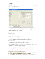
2.5 Indicator Lights Introduction
The IP MODEM provides three indicator lights: “Power”, “ACT”, “Online”, “GPS”.
Indicator
Light
State
Introduction
Power
ON
IP MODEM is powered on
OFF
IP MODEM is powered off
ACT
BLINK
Data is communicating
OFF
No data
Online
ON
IP MODEM has logged on network
OFF
IP MODEM hasn’t logged on network
GPS
ON
GPS data is communicating
OFF
No GPS data is communicating
F7X14 Terminal
Block Interface
User Device
(DB9M)
User Device
1
2
3
4
5
6
7
8
9
10
11
12
RX
GND
TX
A
B
IO1
IO2
IO3
IO4
PWR
GND
IO5
+
Anode
-
Cathode
A
B
F7X14 Terminal
Block Interface
Communication Interface: RS232
Communication Interface: RS485
1
2
3
4
5
6
7
8
9
10
11
12
RX
GND
TX
A
B
IO1
IO2
IO3
IO4
PWR
GND
IO5
1
2
3
4
5
6
7
8
9
GND
TX
RX
+
Anode
-
Cathode
RX


