background image

Page 10

For technical questions, please call 1-888-866-5797.

Item 57336 


SA

FE

TY

OP
ERA

TI

O

N

MAINT

ENANC

E

IN

ST

ALLA

TI

O

N

Operating Instructions

  Read the ENTIRE IMPORTANT SAFETY INFORMATION section at the beginning of this 

manual including all text under subheadings therein before set up or use of this product.

Compressor Area Set Up

1.  Designate a work area that is clean and well-lit.  

The work area must not allow access by 

children or pets to prevent injury.

2.  Locate the Compressor on a flat level surface to 

ensure proper pump lubrication and to prevent 

damage to the unit.  Keep at least 12

 of space 

around the unit to allow air circulation.

3.  Route the power cord from the compressor 

to the grounded wall outlet, along a safe path 

without creating a tripping hazard or exposing 

the power cord to possible damage.

General Operation

1.  Close the Drain Valve.

2.  Close the in-line Shutoff Valve between 

the compressor and the air hose.

3.  Plug the Power Cord into a grounded 

120 VAC electrical outlet.

4.  Pull the ring on Safety Valve to release pressure.

5.  Turn the Power Switch ON (AUTO) .

6.  Allow the Air Compressor to build 

up pressure until it cycles off.

Note:

 At the beginning of the day’s first use 

of the Air Compressor, check for air leaks by 

applying soapy water to connections while the 

Air Compressor is pumping and after pressure cut-

out.  Look for air bubbles.  If air bubbles are present 

at connections, tighten connections.  Do not use the 

Air Compressor unless all connections are air tight, 

the extra air leaking out will cause the compressor to 

operate too often, increasing wear on the compressor.

Note:

 As long as the Power Switch is ON (AUTO), the 

operation of the Air Compressor is automatic, controlled 

by an internal pressure switch.  The Compressor will 

turn on automatically when the air pressure drops to 135 

PSI, and will turn off automatically when the 

air pressure reaches 175 PSI.   

WARNING! TO PREVENT SERIOUS 

INJURY AND DEATH FROM 

EXPLOSION:


Do not adjust the internal 

pressure switch.  

Any change to the 

automatic pressure levels may cause excess pressure to 

accumulate, causing a hazardous situation.

7.  Pull out the Regulator and adjust so that the air 

output is enough to properly power the tool, but 

the output will not exceed the tool’s maximum air 

pressure at any time.  Turn the knob clockwise to 

increase the pressure and counter-clockwise to 

decrease pressure.  Adjust the pressure gradually, 

while checking the air output gauge to set the 

pressure.  Push in Regulator when finished.

8.  Make sure the air tool’s throttle or switch is in the 

off position.  Connect the air tool to the air hose.

9.  Open the in-line Shutoff Valve.

10. Use the air tool as needed.

11.  After the job is complete, turn the Power Switch OFF.

12. Unplug the Air Compressor.

13. Close the in-line Shutoff Valve.

14. Bleed air from the tool then disconnect the tool.

15. Drain Tank according to 

Draining Moisture 

from the Tank on page 12.

16. Clean, then store the Air Compressor indoors.

Emergency Depressurization

If it is necessary to quickly 

depressurize

 the Compressor, turn the Power Switch OFF.  

Then, pull on the ring on the Safety Valve to quickly release stored air pressure.

Summary of Contents for 57336

Page 1: ...ence 21l When unpacking make sure that the product is intact and undamaged If any parts are missing or broken please call 1 888 866 5797 as soon as possible Copyright 2021 by Harbor Freight Tools All...

Page 2: ...tions for future reference The warnings precautions and instructions discussed in this instruction manual cannot cover all possible conditions and situations that may occur It must be understood by th...

Page 3: ...the compressor for operations different from those intended could result in a hazardous situation 5 Service a Have your compressor serviced by a qualified repair person using only identical replaceme...

Page 4: ...sors with Three Prong Plugs 1 In the event of a malfunction or breakdown grounding provides a path of least resistance for electric current to reduce the risk of electric shock This compressor is equi...

Page 5: ...ard conditions NPT National pipe thread tapered NPS National pipe thread straight Double Insulated V Volts Alternating Current A Amperes Specifications Electrical Rating 120VAC 60Hz 15A Air Outlet Siz...

Page 6: ...use of this product TO PREVENT SERIOUS INJURY FROM ACCIDENTAL OPERATION Turn the Power Switch OFF and unplug the Air Compressor from its electrical outlet before assembling or making any adjustments t...

Page 7: ...ower Cord 4 Turn the Power Switch ON AUTO 5 Let the unit run for 30 minutes Air will expel freely through the Drain Valve 6 Turn the Power Switch OFF 7 Unplug the Power Cord and close Drain Valve Air...

Page 8: ...A Air Hose Connects air to tool B Filter Prevents dirt and condensation from damaging tool or workpiece C Regulator Adjusts air pressure to tool D Lubricator optional For air tool lubrication E Couple...

Page 9: ...r vibration reduction E Main Air Line 3 4 minimum recommended Distributes air to branch lines F Ball Valve To drain moisture from system G Branch Air Line 1 2 minimum recommended Brings air to point o...

Page 10: ...ons are air tight the extra air leaking out will cause the compressor to operate too often increasing wear on the compressor Note As long as the Power Switch is ON AUTO the operation of the Air Compre...

Page 11: ...e damaged equipment If abnormal noise or vibration occurs have the problem corrected before further use Cleaning Maintenance and Lubrication 1 BEFORE EACH USE inspect the general condition of the air...

Page 12: ...to open it Tilt Compressor forward to drain 4 When all the pressure and moisture are released close the Drain Valve Air Filter Maintenance 1 Remove Air Inlet Filters by turning them counterclockwise 2...

Page 13: ...ARRANTY OF ANY KIND TO THE BUYER THAT HE OR SHE IS QUALIFIED TO MAKE ANY REPAIRS TO THE PRODUCT OR THAT HE OR SHE IS QUALIFIED TO REPLACE ANY PARTS OF THE PRODUCT IN FACT THE MANUFACTURER AND OR DISTR...

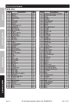
Page 14: ...3 Bolt M4 8 6 44 Cylinder Head Seal 2 45 Cylinder Cap 2 46 Washer 8 47 Spring Washer 8 48 Bolt M6 70 8 49 T Cock 1 50 Easy Start Valve 1 51 Seal 4 52 Tube 2 Part Description Qty 53 Cylinder Head Guard...

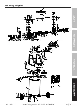
Page 15: ...Page 15 For technical questions please call 1 888 866 5797 Item 57336 SAFETY OPERATION MAINTENANCE INSTALLATION Assembly Diagram...

Page 16: ...amages so the above limitation of exclusion may not apply to you THIS WARRANTY IS EXPRESSLY IN LIEU OF ALL OTHER WARRANTIES EXPRESS OR IMPLIED INCLUDING THE WARRANTIES OF MERCHANTABILITY AND FITNESS T...

Reviews: