background image

Rev. 1.8 

505 Keystone Rd, Southampton, PA 18966, USA 

(877) 497 6937

.


[email protected]


www.fortresspower.com


Table of Contents 

General Information ........................................................................................................................................... 3 

Specifications .................................................................................................................................................... 6 

Features ............................................................................................................................................................ 7 

Registering for the Fortress Power Warranty ..................................................................................................... 8 

1. SAFETY ........................................................................................................................................................ 8 

1.1 General safety precautions ....................................................................................................................... 8 

2. IMPORTANT NOTES .................................................................................................................................... 9 

2.1 Transportation and Handling .................................................................................................................... 9 

2.2 Storage .................................................................................................................................................... 9 

2.3 Response to emergency situations ......................................................................................................... 10 

2.4 Charge/Discharge .................................................................................................................................. 10 

2.5 Charging notes ....................................................................................................................................... 11 

2.6 System sizing ......................................................................................................................................... 12 

3. PRODUCT INTRODUCTION ....................................................................................................................... 13 

3.1 Technical data ........................................................................................................................................ 13 

3.2 Unboxing Check list ................................................................................................................................ 14 

3.3 Accessories and Part Numbers .............................................................................................................. 14 

4. INSTALLATION ........................................................................................................................................... 15 

4.1 Tools & Materials ................................................................................................................................... 15 

4.2 Inspection before Installation .................................................................................................................. 15 

4.3 Installation Considerations ..................................................................................................................... 16 

4.4 Installation Steps .................................................................................................................................... 16 

4.4.1. Mounting on a Server Rack ............................................................................................................. 16 

4.4.2. Mounting the battery pack to a wall ................................................................................................. 18 

4.4.3 Floor standing installation ................................................................................................................ 19 

4.4.4 Connecting the battery to the Charge Controller and/or Hybrid Inverter ........................................... 19 

4.4.5 Using RS485 and CAN Communication ........................................................................................... 19 

4.4.6 Using a single eFlex battery pack .................................................................................................... 21 

4.4.7  Parallel Connection of >1 eFlex battery.......................................................................................... 22 

4.6 System Commissioning .......................................................................................................................... 24 

Summary of Contents for eFlex 5.4

Page 1: ...nufactured at the highest quality standards It comes with large power capacity and a fast charging and continuous discharge power LFP Chemistry also has nearly twice the cycle life of other Lithium technologies such as NMC The proprietary architecture and BMS eliminate the need for cooling or ventilation which creates a nearly 99 efficient round trip conversion of energy The Fortress Lithium Batte...

Page 2: ...Rev 1 8 505 Keystone Rd Southampton PA 18966 USA 877 497 6937 techsupport fortresspower com www fortresspower com 2 ...

Page 3: ...stries Do not mix different capacity batteries do not mix batteries from different installations or job site CAUTION Verify polarity at all connections with a standard voltmeter before energizing the system Reverse polarity at the battery terminals will void the Warranty and destroy the batteries Do not short circuit the batteries Retrofitting Fortress Lithium batteries to an existing system is no...

Page 4: ...2 6 System sizing 12 3 PRODUCT INTRODUCTION 13 3 1 Technical data 13 3 2 Unboxing Check list 14 3 3 Accessories and Part Numbers 14 4 INSTALLATION 15 4 1 Tools Materials 15 4 2 Inspection before Installation 15 4 3 Installation Considerations 16 4 4 Installation Steps 16 4 4 1 Mounting on a Server Rack 16 4 4 2 Mounting the battery pack to a wall 18 4 4 3 Floor standing installation 19 4 4 4 Conne...

Page 5: ...hsupport fortresspower com www fortresspower com 5 5 OPERATION 25 5 1 Charging 25 5 1 1 Please follow the following steps to use the charger to charge the battery 25 5 2 Discharging 25 5 3 Parameter set up guide for Charger Inverter 26 6 DIAGNOSTIC INTERFACE GUIDE 27 ...

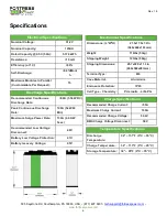
Page 6: ...w Voltage Protection 41V Battery recovery Voltage 45V Electrical Specifications Nominal Voltage 51 2V Nominal Capacity 105AH Rated Capacity 0 5C 50A 5 374 kWh Resistance 10 mΩ Efficiency at 1C 99 Self Discharge 0 8 Mont h Maximum Modules in Parallel Customizable Per Request 15 Temperature Specifications Discharge Temperature 32 131 F 0 C 55 C Charge Temperature 32 113 F 0 C 45 C Storage Temperatur...

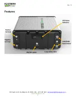
Page 7: ...Rev 1 8 505 Keystone Rd Southampton PA 18966 USA 877 497 6937 techsupport fortresspower com www fortresspower com 7 Features ...

Page 8: ...isconnected from the Battery Pack wiring Wiring must be carried out by qualified personnel Battery Pack is not user serviceable High voltage or current is present in the device The electronics inside the Battery Pack are vulnerable to electrostatic discharge Observe the following precautions Risks of explosion Do not subject the battery pack to strong impacts Do not crush or puncture the battery p...

Page 9: ... clothing and footwear and using electrically insulated tools are required when working with Fortress Power Lithium Batteries Cover restrain or remove jewelry or conductive objects metal bracelets rings belt buckles metal snaps zippers etc when working with any electrical or mechanical device Cover or restrain long hair and loose clothing when working with any electrical or mechanical device 2 IMP...

Page 10: ... Rinse eyes with flowing water for 15 minutes and seek medical attention Contact with skin Wash the affected area thoroughly with soap and water and seek medical attention Ingestion Induce vomiting and seek medical attention Fire In case of fires make sure that the extinguisher is available near the battery pack If possible move the battery pack to a safe area before it catches fire Note FM 200 fi...

Page 11: ...os occur the battery must be charged before use otherwise the battery damage caused is not covered by the free warranty The battery has undergone long term transportation or storage and has not been operated in accordance with the supplementary power requirements The battery is in a disabled or standby state for a long period of time during transportation or storage The battery was vented during u...

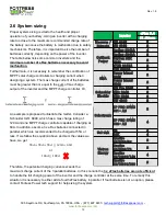
Page 12: ... max charge rating of 120A and one MPPT charge controller capable of charging at 60A In addition assume 3 x eFlex batteries connected in parallel which are recommended to be charged at 55A or less If we follow the equation above and sum the values we have we get 55𝐴 55𝐴 55𝐴 120𝐴 60𝐴 or 165𝐴 180𝐴 Therefore the potential charging current exceeds the maximum charge current of the 3 parallel batteries...

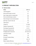
Page 13: ...arge Current Continuous A 100 Recommend discharge current A 68 Max Discharge Current Continuous A 100 Max Pulse Current for 5sec A 130 Capacity Ah 105 Voltage V 51 2 48 Charging Temperature F 32 113 Discharging Temperature F 32 131 Dimension LxWxH inches 21 5x17 5x7 2 Packaging Dimension inches 25 7x22 9x11 3 Connection Terminal M8 Weight lb 116 Enclosure Protection Rating IP65 Scalability Up to 1...

Page 14: ...ct sales fortresspower com if interested in these kits Name Fortress Kit Description Item Description kit Quantity Wall mount kit eFlex wall mount kit 10069625 Wall Mount panel 2 10069626 Wall Mount Kits 4 10019875 Hammer screw M6 4 10061513 Hammer nut M6 8mm 4 Side mount kit eFlex side mount kit 10019875 Hammer screw M6 4 10062392 Side Mount Kits 2 10061513 Hammer nut M6 8mm 4 Rack Mount Bracket ...

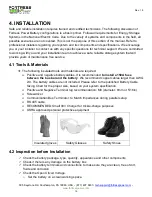
Page 15: ...nce free service 4 1 Tools Materials The following insulated tools and materials are required Positive and negative battery cables It is recommended to install a 150A fuse between the bus bar and the battery We recommend copper cables larger than AWG 2 0 The battery cables are not included Please refer to the published Battery Cable Sizing Chart for the proper size based on your system specificati...

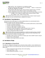
Page 16: ...ions At minimum the eFlex should be protected from inclement weather with a cover enclosure The area is completely waterproof The floor is flat and level Inclination 15 There are no flammable or explosive materials The optimal ambient temperature is within the range from 59 to 95 The temperature and humidity are maintained at a constant level There is minimal dust and dirt in the area IMPORTANT NO...

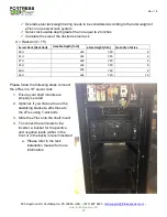
Page 17: ...s to mount the eFlex in a 19 server rack 1 Ensure your shelf mounts are properly secured 2 Optional If you choose to use the stabilizing brackets affix those to the eFlex using T slot bolts 3 Slide the eFlex onto the shelf mount 4 To connect the terminals to the inverter a busbar for the positive and negative leads either in the front or in the back is recommended a Please refer to the rack instal...

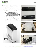
Page 18: ...re the wall and mounting hardware can handle the weight of the batteries 1 Line up the top bracket on the wall a Mark the desired placement using a level to ensure the bracket is horizontal b Affix the mounting bracket into the wall 2 Using the T slot screws fix the male brackets onto the slots in the battery 3 Once all brackets are properly positioned carefully lift the battery with the help of s...

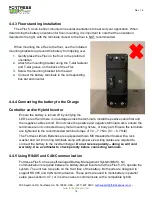
Page 19: ... LED s are off and there is no voltage across the terminals Install the positive cable first and the negative cable second Do not cross the positive and negative terminals also ensure the terminals are not connected to any metal mounting fixture or body part Ensure the terminals are tightened to the recommended terminal torque of 7 0 7 7 Nm 5 1 5 7 ft lb The Fortress Lithium Batteries are equipped...

Page 20: ...controller Below is a sketch of the communication between paralleled batteries If you need to make a communication cable please refer to the pinout diagram for an RJ45 cable below CAUTION Please check with Fortress Power to see if you can use the CAN comm port to connect the battery to your charge controller or battery based inverter ...

Page 21: ...mal operation there must be a description of what the operator should see which LED s are on and what color to verify that all is OK and the inverter can be started 5 Check battery voltage Check that voltage between terminals is between 50 55V If the voltage is too low a slow charging to 50V is needed 6 Put the inverter breaker into ON position Note always turn the eFlex battery on first prior to ...

Page 22: ... The illustration below shows how to connect multiple batteries in parallel Please note the overall voltage is not changed The available amperage from the system is increased with each additional parallel battery In a parallel system with two batteries the available charging and discharging amperage is doubled compared to a single battery Prior to installation check all battery voltages independen...

Page 23: ... Confirm all units complete their self diagnostics and the LED s indicate normal operation what does normal operation look like 5 Turn on the inverter system Note some inverters have high in rush current and need to be pre charged manually or you can choose use BMS pre charge function to start it up This requires the inverter to be turned on first before you turn on the battery Please refer to the...

Page 24: ...ortress Lithium Battery has been installed turn on the entire system to test Once testing has been completed please disconnect the batteries from the load center until your local Utility Inspector is ready to turn on the entire system The charge controllers and inverter monitoring systems can drain the Fortress Lithium Batteries over an extended period when the entire system is not fully operation...

Page 25: ... CAUTION Do not attempt to charge the battery below 32 degrees F 0 degrees C Attempts to charge at subfreezing temperatures can adversely affect State of Health SOH and cycle life and will void the warranty never charge battery if it is frozen never charge a visibly damaged battery 5 1 1 Please follow the following steps to use the charger to charge the battery 1 Connect the charger leads to the b...

Page 26: ...lk Absorb Voltage CV 3 Terminate when charge current drops below 0 05C 4 Unlike Lead Acid batteries Lithium Ferro Phosphate batteries do not require Float Charge Charger Inverter configuration recommendation for best Performance The Battery Parameter Setting Guides with SMA Sol Ark Schneider and Outback Inverters Chargers are available to download on www fortresspower com Resource Recommended oper...

Page 27: ...n there is a communication error between batteries If the problem persists please contact Fortress Power tech support In normal operation the RUN LED light will be on The number of charging lights LED1 4 that are on depends on the battery state of charge Below is a chart that explains the SOC as a function of the charging LED lights Battery status SOC status LED1 LED2 LED3 LED4 Full of rest 100 ON...

Page 28: ... USA 877 497 6937 techsupport fortresspower com www fortresspower com 28 PLEASE CONTACT US FOR TECHNICAL SUPPORT Fortress Power LLC 505 Keystone Road Southampton Pennsylvania 18966 877 497 6937 techsupport fortresspower com www FortressPower com ...

Reviews: