Fortinet FortiTester 2500E Quick Start Manual Download Page 10

10

4. Hold the sides of the transceiver and slide it into the cage

socket until it clicks into place.

5. Press the transceiver firmly into the cage socket with

your thumb.

6. Verify that the transceiver is latched corrtectly by grasping

the sides of the transceiver and trying to pull it out
without lowering the extraction lever.
If the transceiver cannot be removed, it is installed and
latched correctly.
If the transceiver can be removed, reinser it and press
harder with your thumb.
If necessary, repeat  this process until the transceiver is
securely latched into the cage socket.

.

To remove the transceivers

1. Ensure that you are properly grounded.

.

2. If applicable, disconnect the fiber


-optic cable from the

transceiver connector and  install a clean dust plug in the
transceiver’s optical bores..

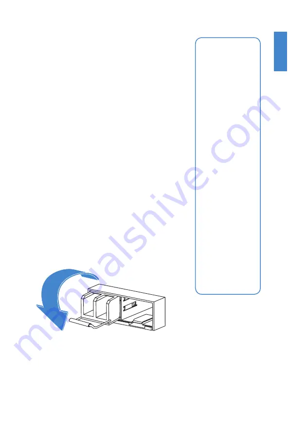
3. Pull the ex trac tion lever out and down to ejec

   t the

transceiver. If you are unable to use your finger to open


the lever, use a small flat-


head screwdriver or other

similar tool to open the lever.

.

4. Hold the sides of the transceiver and carefully pull it away


from the cage socket.

.

5. Replace the cap on the cage socket and place the

removed transceiver into an antistatic bag.

.

Caution:

 Do 

not force the 
transceivers into 
the cage slots. 
If the transceiver 
does not easily 
slide in and click 
into place, it may 
not be aligned 
correctly or may 
be upside down. 
If this happens, 
remove the 
transceiver, realign 
it or rotate it and 
slide it in again.

Note:

 Follow 

proper fi ber-
optic handling 
procedures when 
installing and 
removing
transceivers to 
ensure the devices 
remain clean and 
are not damaged.

Summary of Contents for FortiTester 2500E

Page 1: ...FortiTester 2500E QuickStart Guide...

Page 2: ...nt Fortinet enters a binding written contract signed by Fortinet s General Counsel with a purchaser that expressly warrants that the identified product will perform according to certain expressly iden...

Page 3: ...ionnalit es du produit Protection contre de nouvelles menaces La reistrazione ti permette di usufruire di Supporto Tecnico Nuove funzionalita Proteezione dalle ultime minaccce Debe registrar el produc...

Page 4: ...ester 2500E Quickstart Guide 2 Power cables Ethernet cable Console cable 5 Rubber feet 6 M4 screws for sliding rails handles 2 M6 rack mount screws 2 Sliding rail handles 2 Sliding rails FortiTester 2...

Page 5: ...ortiTester unit into a rack 1 Ensure that the FortiTester unit is placed on a stable surface prior to rack mount installation 2 Assemble the rails and install the system in the rack following the safe...

Page 6: ...pull the chassis inner member out 2 Use the stando s to mount the chassis inner member to the chassis 3 To attach the cabinet outer member of the rail first ensure that the safety lock is in the unloc...

Page 7: ...t the chassis inner member into the cabinet member When you push the chassis back into the cabinet press the trigger down to release the slide from the locked position Release safety lock before mount...

Page 8: ...8...

Page 9: ...ch time that you are inserting a transceiver Caution Transceivers are static sensitive devices Use an ESD wrist strap or similar grounding device when handling transceivers Do not install or remove tr...

Page 10: ...able from the transceiver connector and install a clean dust plug in the transceiver s optical bores 3 Pull the extraction lever out and down to eject the transceiver If you are unable to use your fin...

Page 11: ...e and then into a grounded electrical outlet or a separate power source such as an uninterruptible power supply UPS or a power distribution unit PDU If the appliance has a redundant power supply conne...

Page 12: ...t port default subnet For example from the Windows 7 Control Panel go to Network and Sharing Center Click the Local Area Connection link and then click the Properties button Select Internet Protocol V...

Page 13: ...management computer select the COM port and use the following settings Baud Rate 9600 Data bits 8 Parity None Stop bits 1 Flow Control None 3 Press Enter on your keyboard to connect to the CLI 4 Logi...

Page 14: ...eboots the system MGMT Dedicated Gigabit Ethernet Management Port for system management Console Optional connection to the management computer Provides access to the CLI Grounding Screws Provides extr...

Page 15: ...t Ethernet ports for connections to your DUT Power Switch To turn the power ON OFF Power Supply Warning Buzz Reset Button To disable the power supply warning buzz Power Connections 100 240V AC 50 60 H...

Page 16: ...wered on Power Green The unit is ON OFF The unit is OFF Status OFF System is normal Green Minor system alarm Red System failure HDD Flashing Amber HDD in use MGMT Port Link Activity Flashing Amber Tra...

Page 17: ...ng Receiving data O Port is not in use PORT 1 4 Speed O Port is not in use 17 Power Supply Status Green Power supply is opera ng normally Red Power supply is not connected to power or mechanical fail...

Page 18: ...ion of equipment nameplate ratings should be used when addressing this concern Surtension Il convient de prendre l ensemble des pr cautions n cessaires lors du branchement de l quipement au circuit d...

Page 19: ...Any changes or modifications to this product not expressly approved by the party responsible for compliance could void the user s authority to operate the equipment Industry Canada Equipment Standard...

Page 20: ...hedules and location of training programs in your area http www fortinet com support training html Technical Discussion Forums Communicate with other customers and Fortinet partners about Fortinet pro...

Reviews: