Fortinet FortiADC 1200F Quick Start Manual Download Page 8

15

14

Install the Appliance


Safety Precautions

1.  Check that the inner rails are secured to the appliance
2.  Inspect that the rack posts and outer rails are secured and level 
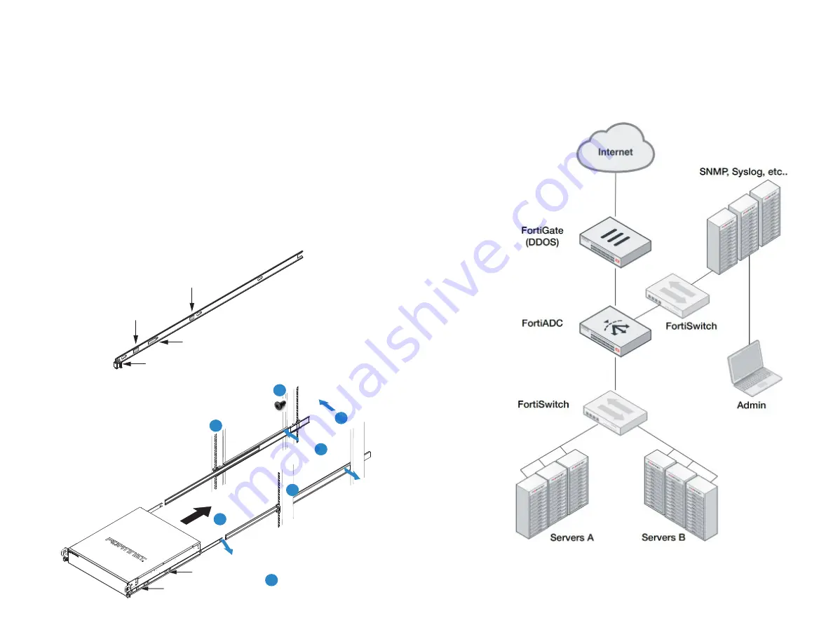
Rail Installation

3.  Slide the middle outer rails forward until they fully extend and lock into place
4.  Using a lifting device, lift the appliance and align the inner rails with the middle rails
5.  Slide the appliance and inner rails into the middle rails until there is a stop 

System Lock

6.  Apply even pressure and slide the release tabs outward while sliding the appliance all 

the way into the rack until the system release tabs click and lock into position

7.  Use four rack screws (not provided) to secure the appliance to the rack 

System Release Button

Inner Rail Metal Clip

Release Tab

System Lock Out Tab

Release Tab

System Lock Out Tab

System Lock Out Tab

Release Tab

1

6

7

2

3

4

5

Check Rail Locks

Inspect Posts

Extend Rails

Align Rails

Slide Rails

Deployment

Fully integrate with Fortinet's Security Fabric to optimize network visibility, 
load balancing, and user authentication with your new FortiADC.

Summary of Contents for FortiADC 1200F

Page 1: ...FortiADC 1200F QuickStart Guide ...

Page 2: ...nding commitment by Fortinet and Fortinet disclaims all warranties whether express or implied except to the extent Fortinet enters a binding written contract signed by Fortinet s General Counsel with a purchaser that expressly warrants that the identified product will perform according to certain expressly identified performance metrics and in such event only the specific performance metrics expre...

Page 3: ...ement default IP is 192 168 1 99 HA RJ45 GE high availability port Ports 17 to 24 SFP 10 GE GE SFP slots Ports 9 to 16 SFP GE SFP slots Ports 1 to 8 RJ45 GE SFP slots Green Link established at 10 or 1 Gbps Flashing Green Transmitting data Off No link established 1 Power Supply Alarm Amber Power supply failure Off Normal operation System LED Indicators Power Supply Fan Alarm Amber Fan failure Off N...

Page 4: ...50 60Hz Redundant Power Supplies x2 48V DC to 60V DC 20A Power Switch turns the power ON OFF Power Switch turns the power ON OFF 4 2 2 3 3 1 1 Green Power supply operating normally Flashing Green 1 sec AC input but in Active Standby mode Amber AC input power failure second power supply operating normally Off No AC input DC Power Supply Indicator 4 Green PSU operating normally Flashing Green 1 sec ...

Page 5: ... Installation Plug in your device to a power outlet using the provided DC power cables Assemble the power cables using the supplied power connector Pin 1 Pin 2 Pin 2 Pin 3 Pin 1 Pin 3 DC PSU1 DC PSU2 Note Pin 1 is Negative Pin 2 is Positive Pin 3 is Ground Cables and terminal lugs are not included The wires are rated between 24 10 AWG Note We recommend connecting your FortiADC to an uninterruptibl...

Page 6: ...sliding out ensure that it is locked when installing the appliance Prevent Electrostatic discharge ESD damage by wearing antistatic devices Do not place heavy objects on the appliance What You Will Need Philips screwdriver level tape measure Rack provided cage nuts and screws A lifting device or additional support ESD antistatic gear https video fortinet com http support fortinet com Rail Assembly...

Page 7: ...he remaining inner rail Align Rail Metal Clip Inner Rail Inner Rail Attach the Outer Rails to the Rack Front Outer Rail 1 Place an outer rail against a side of the rack 2 Align the front outer rail with the front of the rack 3 Push the front outer rail mounting pins into the rack post holes 4 Lock the locking latch to safely secure the front outer rail to the post Rear Outer Rail 5 Extend the rear...

Page 8: ... is a stop System Lock 6 Apply even pressure and slide the release tabs outward while sliding the appliance all the way into the rack until the system release tabs click and lock into position 7 Use four rack screws not provided to secure the appliance to the rack System Release Button Inner Rail Metal Clip Release Tab System Lock Out Tab Release Tab System Lock Out Tab System Lock Out Tab Release...

Page 9: ... Local Setup An easy to use GUI compatible with most web browsers To minimize scrolling the screen resolution should be at least 1280 x 1024 pixels A B Ethernet Cable 1 Connect Port 1 to the Management Computer using the supplied Ethernet cable 2 Enable DHCP or set the Management Computer s IP and subnet to Static IP Address 192 168 1 1 Subnet Mask 255 255 255 0 3 Visit 192 168 1 99 in a web brows...

Page 10: ...ic Settings Please refer to the admin guide found on docs fortinet com for detailed instruction on configuring your FortiADC Basic Network Settings 1 Once you have installed your FortiADC and configured your management interface we recommend setting the following Administrative password System time and date Network interfaces DNS 2 Test the connectivity between devices 3 Register your product if y...

Page 11: ...tif assurant une protection contre les courts circuits et le câblage Ainsi il est recommandé de tenir compte du numéro d identification de l équipement Reliable Earthing Reliable earthing of rack mounted equipment should be maintained Particular attention should be given to supply connections other than direct connections to the branch circuit e g use of power strips Fiabilité de la mise à la terr...

Page 12: ...pment is operated in a commercial environment This equipment generates uses and can radiate radio frequency energy and if it is not installed and used in accordance with the instruction manual it may cause harmful interference to radio communications Operation of this equipment in a residential area is likely to cause harmful interference in which case the user will be required to correct the inte...

Page 13: ...Fortinet com ...

Reviews: