


Front panel connectors
FIM-7920E interface module
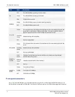
LED
State
Description
HA
Off
The FIM-7920E is operating in normal mode.
Green
The FIM-7920E is operating in HA mode.
Red
A failover has occurred
POWER
Green
The FIM-7920E is powered on and operating normally.
Off
The FIM-7920E is powered off.
C1 to C4
Green
The correct cable is connected to the interface and the connected equipment has
power and is connected at 100Gbps or 40Gbps. If the port is split the LED will
light as long as at least one of the 10Gbps connections is active.
Flashing
Green
Network activity at the interface.
Off
No link is established.
M1 and M2
Green
The correct cable is connected to the interface and the connected equipment has
power.
Flashing
Green
Network activity at the interface.
Off
No link is established.
MGMT1-4
Link/Act
Solid
Green
Indicates this interface is connected with the correct cable and the attached
network device has power.
Blinking
Green
Indicates network traffic on this interface.
Off
No Link
MGMT1-4
Speed
Green
Connection at 1Gbps.
Amber
Connection at 100Mbps.
Off
Connection at 10Mbps.
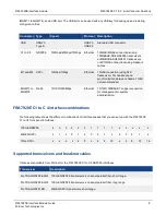
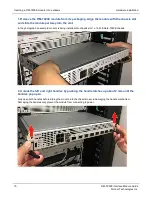
Front panel connectors
You connect the FIM-7920E to your 100Gbps networks using the C1 to C4 front panel QSFP28 interfaces. The
front panel also includes M1 and M2 SFP+ interfaces for the base channel, four Ethernet management interfaces
7
FIM-7920E Interface Module Guide
Fortinet Technologies Inc.
Summary of Contents for FIM-7920E
Page 1: ...FIM 7920E Interface Module Guide 7000 ...
Page 4: ...China 26 ...