Fortec Star Distec XTRA-Line 37 Bartype High Bright IoT User Manual Download Page 9

First Installation

9

4. 

First Installation

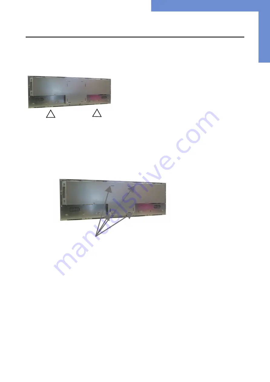
Position of connectors and controls

All the connectors for power and cables are located at the bottom of the back side of the display. The OSD keyboard is located at the 

top of the back side.


     Position 

of 

the 

OSD 

keyboard


Position of the connectors for power (right)

Position of the connector for ambient light sensor (ALS if 2500 cd panel) and signal cables (left)

Position of the OSD keyboard (middle/ bottom)

Mounting with VESA compliant monitor brackets


The XTRA Line monitor has an integrated VESA mounting.

The operating position of the device is perpendicular (90 degrees to the floor). For wall mounting, the permissible tilt angle is observed.

VESA formats: 

VESA 200x200

VESA- mounting points

Summary of Contents for Distec XTRA-Line 37 Bartype High Bright IoT

Page 1: ...User Manual XTRA Line Bartype 37 XTRA Line Bartype monitors 93 98 cm 37 202107_Manual_XTRA_Line_37_EN pdf...

Page 2: ...anual in parts or entirely without the previous authorization of Distec is prohibited Distec is not liable for errors and collateral or subsequent damage which result from supply deployment or any oth...

Page 3: ...2 Scope of Delivery 5 3 General Safety Regulations 6 4 First Installation 9 5 Ambient Light Sensor 14 6 XTRA Line Bartype 37 PME 15 7 XTRA Line Bartype 37 IoT 23 8 Maintenance 26 9 Guarantee Service 2...

Page 4: ...s are also available for download from Data Display Group web site www distec de en service downloads moni tor downloads XTRA Line bartype monitor versions XTRA Line 37 Bartype High Bright Video PME M...

Page 5: ...ollowing accessories are included in the shipment Note Pictures can differ from actually supplied products Product information DP cable Power cable Remote control ALS sensor Cable for ALS Cable may va...

Page 6: ...Before system start up slowly adjust the monitor temperature to the ambient temperature Do not expose device to direct heat ra diation In case of condensation please wait minimum 12 hours before setti...

Page 7: ...several devices into a single socket Do not use damaged or loose sockets to plug in the device Plug the device in earthed sockets only Operate the device with our power cables included in the deliver...

Page 8: ...scratched easily Therefore please use the prescribed cloth only Please use a soft moist cloth for cleaning For cleaning the screen please only use commercially available screen cleaner Do not spray th...

Page 9: ...osition of the connectors for power right Position of the connector for ambient light sensor ALS if 2500 cd panel and signal cables left Position of the OSD keyboard middle bottom Mounting with VESA c...

Page 10: ...floor Pay attention to the permissible tilt angle for wall mounting The device can be operated both in landscape mode and in portrait mode The information is for positioning to note on the back of the...

Page 11: ...Line bartype displays require a voltage of 110V 230V AC Note Install all data cables to external devices before connecting the display to power Switch the on of switch in position off Connect the pow...

Page 12: ...First Installation 12 OSD navigation through IT Remonte Control Alternative to the external OSD keypad the Prisma IIIA can also be controlled through a remote control device...

Page 13: ...st Installation 13 OSD navigation through IT Remonte Control second variant of remote control Alternative to the external OSD keypad the Prisma IIIA can also be controlled through a remote control dev...

Page 14: ...alled the right way round Furthermore the cable must first be threaded into the housing with the noses now press the connector down and clip it in Here are two pictures for a better understanding In t...

Page 15: ...ttons of XTRA Line Bartype 37 Video PME series Connecting to a PC with VGA cable Connecting to a PC with HDMI DVI cable VGA RGB USB Touch DisplayPort HDMI USB remote OSD Headphones LED OSD Keyboard Po...

Page 16: ...OSD functions of the monitor can be controlled via OSD key pad The OSD allows selection of input source and fine tuning of various functional parameters like brightness contrast etc The OSD control c...

Page 17: ...u when in main Confirm entry when in main Cursor down when in main or in sub menu Cursor slider to the left when in main or in sub menu Cursor up when in main or in sub menu Cursor slider to the right...

Page 18: ...tion adjustment Sharpness Panel sharpness adjustment Color Opens the color sub menu Color Sub Menu Auto Performs auto color adjustment Color Temp Allow selection of different color temperature schemes...

Page 19: ...function is a slider to adjust the sample clock of the analogue interface This is helpful for improving the image quality for non standard display modes Position Used to alter placement of the image M...

Page 20: ...source OSD settings Sub menu for OSD settings Factory reset Sub menu for Factory Reset EDID settings Sub menu for EDID settings FW Revision Firmware revision OSD Revision OSD revision Input Sub Menu...

Page 21: ...imer settings Rotation Sub menu for rotation settings Position Sub menu for image position Transparency Slider to set transparency Timer Sub Menu Timer Selects how many seconds the OSD will remain act...

Page 22: ...XTRA Line Bartype 37 PME 22 Reset Sub Menu Reset Performs factory reset EDID Write Protect Sub Menu Write protect EDID write protect on off...

Page 23: ...there is a risk of explosion Always replace the battery with another one of the same type Supply empty batteries to the local waste battery return system Please also observe the notes in chapter Disp...

Page 24: ...ype 37 IoT 24 Connecting to a PC using a cross over cable Connecting to an USB stick or keyboard mouse Connecting active speakers Connecting a signal source using a HDMI cable LAN LAN USB Line out Lin...

Page 25: ...dule It is only used for the first commissioning of the monitors The IoT Monitor can be equipped and programmed by the customer with its own operating system image For this the USB port on the back of...

Page 26: ...responsible and which include but are not limited to the following Unauthorized opening or disassembling of the product Faulty maintenance by non observation of maintenance instructions Inappropriate...

Page 27: ...e of these guidelines may have effects on warranty Guarantee Processing Group RMA process In order to avoid unnecessary charges it is important to adhere to the RMA regulations Products must be packed...

Page 28: ...ervice return rma 10 Disposal Disposal of old devices If the acquired Distec product is to be disposed of must be implemented into national law the Directive 2012 19 EU Disposal of batteries Applicabl...

Page 29: ...installed and used in accordance with the instruction manual may cause harmful interference to radio communications Operation of this equipment in a residential area is likely to cause harmful interfe...

Reviews: