FORS MW C3 Instruction Manual Download Page 3

CRANE RANGE

www.forsmw.com

3

1 INTRODUCTION

This instruction manual is intended for FARMA cranes, and contains information for safe use.  This crane 
is only intended to be used from the tractor. FARMA cranes are intended for self-employed work in 
the fields of agriculture and forestry. The product is particularly useful for handling round timber, fod-
der, fertiliser, sand, loose fertiliser, large sacks, etc. With forestry, the cranes are intended for automatic 
timber transportation, as well as for basic professional work when the model’s permitted lifting torque 
permits. The permitted lifting forces may not be exceeded under any circumstances. For information 
about permitted load, see the movement pattern on the trailer and in the instruction manual. 

Even if you have experience of this type of product, we recommend that you read our instructions care-
fully in order to familiarise yourself with the product. The instructions contain information that is vital 
for safety and efficiency, as well as to ensure the validity of the factory guarantee. When the product 
you have purchased is delivered, check that is has not sustained any delivery or transport damage. If 
there should be any such damage, or if any parts are missing, contact your dealer immediately. 

It is the responsibility of the user to inform himself regarding the use of the product and to follow the in-
structions carefully. It is also the responsibility of the user to ensure that attachments and connections 
to the vehicle are designed and adapted in such a way that they satisfy the crane’s technical data by a 
clear margin. It is the responsibility of the user, for example when installing a loose crane on equipment 
other than a FARMA trailer, to ensure that the vehicle has the necessary capacity to cope with the lifting 
and slewing torques that the crane is designed to handle. 

Fors MW reserves the right to make changes to equipment and maintenance instructions and to revise 
its data without prior notice. 

Fors MW conforms to ISO  for safety marking in accordance with the EC directive //EC.

Manufacturer:     Dealer: 

AS FORS MW
TULE 30
765 05 SAUE
Tel: + 372 679 00 00
www.forsmw.com


EG – Försäkran om överensstämmelse med direktiv 2006/42/EG 

EU-declaration of Conformity 2006/42/EG 


Tillverkare: 

Manufacture: 


Fors MW AS 

Tule 30 

76505 Saue 

Estland 


Den tekniska dokumentationen är sammanställd av Leif Fors;


The technical file is compiled by Leif Fors;  


Försäkrar härmed att denna utrustning: 

Hereby confirm that this equipment:  


1.


Fordonstyp/Vehicle type:  

2.


Tillverkare/Manufacture: (XXX)  

3.


Serienummer/Chassis number: 

XXXX


4.


Tillverkningskod/Manufacture code: 

XXXX


5.


Tillverkningsår/Manufacture year: 

XXXX


Är tillverkad i överensstämmelse med direktiv 2006/42/EG och kan användas monterad 

tillsammans med annan utrustning för att utgöra en komplett maskin.  

Is manufactured accordingly to demands in directive 2006/42 EG and therefore can be used 

mounted together with other equipment to provide a machine.  


Utrustningen får ej tas i bruk förrän den maskinen eller anläggningen som den skall ingå i 

överensstämmer med kraven i EG´s maskindirektiv.  

The equipment can’t be used before the machine or the formation that it will take place in, is 

accordingly to the demands of the EG machine directive. 


Signatur: 


Datum/Plats: 

Signature:                                                                                Date/Place:


Leif FORS, CEO                                                                    Saue, 25.11.2009 


Tule 30 

765 05 Saue 

Estonia 

Tel: +372 679 00 00 

Fax: +372 679 00 01 

Reg. no. 10094723 

E-mail: [email protected] 

Webb: www.forsmw.com 

VAT-no. EE100189685 


Summary of Contents for C3

Page 1: ...INSTRUCTION MANUAL Instruction manual Cranes v2 2015 EN ...

Page 2: ...R SAFETY DURING SERVICE MAINTENANCE 14 3 3 DAILY INSPECTION 15 3 4 LUBRICATION SCHEDULE 16 3 5 TIGHTENING TORQUES 20 3 6 STORAGE 20 4 OPERATING THE CRANE 21 4 1 ASSEMBLING THE CRANE 21 4 2 DESCRIPTION OF FUNCTIONS 21 4 3 INSTALLING THE CRANE ON A TRACTOR 22 4 4 DISMANTLING CRANE WITH THREE POINT LINKAGE 23 4 5 INSTALLING THE CRANE ON A TRAILER 24 4 6 WORKING WITH THE CRANE 25 4 7 TEST OPERATING TH...

Page 3: ...or example when installing a loose crane on equipment other than a FARMA trailer to ensure that the vehicle has the necessary capacity to cope with the lifting and slewing torques that the crane is designed to handle Fors MW reserves the right to make changes to equipment and maintenance instructions and to revise its data without prior notice Fors MW conforms to ISO for safety marking in accordan...

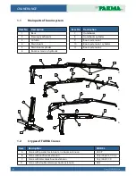
Page 4: ...ane with telescopic boom extension C4 2 C6 3 C7 0 D Crane with double telescopic boom extension C8 5 Item No Description 1 Base 2 Slewing mechanism 3 Column 4 Main boom 5 Main boom cylinder 6 Boom extension hydraulic Item No Description 7 Outerboom 8 Outerboom cylinder 9 Boom extension 1 10 Boom extension 1 cylinder 11 Boom extension 2 1 2 3 4 5 6 7 6 8 7 9 6 4 5 7 8 4 5 7 8 4 5 6 7 8 9 10 4 5 6 7...

Page 5: ...g a crane requires a high level of expertise as well as knowledge about the machine you are using It is important for you to acquire knowledge and to train with regard to the crane s behaviour Practice the movement pattern and always work with smaller loads until you are completely familiar with the crane Take care to ensure that nobody is within the safety zone 20 m FARMA cranes are intended for ...

Page 6: ...r care when loading and unloading heavy materials Never use the loader during transport Stop working by lowering the crane and the grapple onto a firm surface switch off the engine en gage the parking brake and remove the ignition key to prevent unauthorised usage The crane is not intended for lifting people Take great care when loading and unloading in the vicinity of power lines Maintain the saf...

Page 7: ...f clamping injuries There is a risk of clamping or crushing inju ries during work and maintenance Safety distance 20 metres This decal shows the importance of taking great care when working within the crane s safety zone Always keep a close eye on and monitor the crane s safety zone Carelessness can result in direct danger to life Lubrication This decal is used to show the importance of regular lu...

Page 8: ... the data contained on the plate Movement pattern Each FARMA crane is supplied with the crane s movement pattern Ensure that the crane has this plate and check the data contained on the plate Warning regarding remotely started machine components If the crane is equipped with a winch and or radio control of crane functions these can be started without anybody being in contact with the crane Ensure ...

Page 9: ...gs to prevent the lumber trailer from tipping Always maintain a visual check on the work area Do not work under conditions where there could be a risk of clamping injuries or some other injury Only use grapples that are correctly dimensioned for the work task Always pay attention when working close to electrical cables Main tain a safe distance Bear in mind the risk of unforeseen movements If the ...

Page 10: ...he tractor s engine and lower the load to the ground immediately Disconnect the hydraulic flow Repair the rupture Take care to clean up any oil that has run down to the ground Hand in waste to an appropriate waste management facility If the rupture is in the main pressure hose from the tractor to the controls you must stop the oil flow by disconnecting the lever control for the tractor s hydraulic...

Page 11: ...ng Traffic rules are there to be followed Comply with the applicable legislation A tractor with a trailer has a longer braking distance than other vehicles Be aware of the risk of skid ding and look out for irregularities in the road surface Note Firmly secure the load and other loose goods 2 5 4 Hydraulic system Note Always read through the relevant safety instructions when connecting and using t...

Page 12: ...ection If this occurs consult a doctor immediately Note When the hydraulic system is brought back into use following repair work be extremely carefully Air in the system can result in unforeseen crane movements You should therefore bleed the system by operating all the cylinders to their limit positions a few times Note When using the hydraulic functions you should use them gently Do not operate t...

Page 13: ... the necessary welding instructions Incorrect welding or ignorance during welding can result in sudden breaks in the structure 2 5 8 Working in extreme conditions The recommended ambient working temperature for this machine is 30 C to 40 C Note that when working in low or high temperatures the level of wear and stress on seals and hoses increases The du rability of the steel is also impaired and c...

Page 14: ... work Always use tools adapted to the purpose Always wear protective clothing and protective goggles Always switch off the tractor s engine Switch off the tractor s engine and remove the key from the ignition If it is necessary for the tractor s engine to be running during certain elements of the service take care to keep parts of your body away from moving machine parts During service work the cr...

Page 15: ...d immediately Damaged hoses must be replaced immediately Check for leaks Leaking hydraulic fluid entails a risk of accidents and can result in serious environ mental damage Note Check all bolted joints and tighten all loose bolts Operate the crane s complete movement pattern to ensure that all functions are intact If necessary lubricate and check the oil level in the turntable housing Avoid high p...

Page 16: ... G2 C5 3 Qty C4 6S C4 6D Qty Lubricant Interval hours work hours 1 Turnhouse 1 1 SAE 80W 90 GL 5 50h 2 Turnhouse bearing 1 1 Lubricating grease 20h 3 Articulated joints 6 x Lubricating grease 50h 3a Articulated joints x 2 Lubricating grease 50h 4 Spherical bearing 6 6 Lubricating grease 50h 5 Rotator link 2 2 Lubricating grease 50h 6 Grapple 8 8 Lubricating grease 20h 7 Extension s wearing surface...

Page 17: ...ting grease 50h 3a Articulated joints x Lubricating grease 50h 4 Spherical bearing 6 Lubricating grease 50h 5 Rotator link 2 Lubricating grease 50h 6 Grapple 8 Lubricating grease 20h 7 Extension s wearing surfaces 2 Lubricating grease 50h Recommended hydraulic oils UTTO or STOU SAE10W 30 SAE 32 SAE 46 PS Use only hydraulic fluids recommended for your tractor hydraulic system by the manufacturer 3 ...

Page 18: ...grease 50h 3a Articulated joints x Lubricating grease 50h 4 Spherical bearing 6 Lubricating grease 50h 5 Rotator link 2 Lubricating grease 50h 6 Grapple 8 Lubricating grease 20h 7 Extension s wearing surfaces x Lubricating grease 50h Recommended hydraulic oils UTTO or STOU SAE10W 30 SAE 32 SAE 46 PS Use only hydraulic fluids recommended for your tractor hydraulic system by the manufacturer 4 3 5 4...

Page 19: ...g grease 50h 3a Articulated joints x Lubricating grease 50h 4 Spherical bearing 6 Lubricating grease 50h 5 Rotator link 2 Lubricating grease 50h 6 Grapple 8 Lubricating grease 20h 7 Extension s wearing surfaces x Lubricating grease 50h Recommended hydraulic oils UTTO or STOU SAE10W 30 SAE 32 SAE 46 PS Use only hydraulic fluids recommended for your tractor hydraulic system by the manufacturer 3 4 4...

Page 20: ...rces the water away from the surfaces and thereby counteracts corrosion and wear To prevent the risk of rust inside the turnhouse cylinder when crane is stored for extended periods it is recommended to fill gear oil up to the plug see 3 3 for picture NB When crane will be taken into action again it is important to detract oil from the turnhouse It means when the crane is in use the oil level must ...

Page 21: ...acquaint himself with the properties of a new crane before starting work The cranes in FARMA s range are hydraulically operated which means that all their functions and move ments are performed by hydraulic components such as cylinders and rotators The hydraulic system is an open system This means that the oil is drawn up by a hydraulic pump from a tank and then routed under high pressure out to t...

Page 22: ... machines Be extremely carefully as there is a risk of you being trapped 1 Connect the drawbar to the fittings in the crane s three point linkage 2 Secure the push rod to the tractor s existing fittings with the end closest to the point where the fittings are secured to the chassis This ensures that the load in the push rod fittings is as small as possible ...

Page 23: ...ng nuts Park the crane backwards with the crane nose resting on the ground so that the crane and the sup port legs are stable Secure the lifting straps so that the crane is well balanced Then lift of the crane together with the three point linkage away from the trailer s vertical guide pipes Roll the trailer back so that the crane can be lowered freely to the ground When installing the three point...

Page 24: ...5 FORS MW Ltd 4 5 Installing the crane on a trailer Lower the crane 1 onto the trailer s mounting plate 2 Lock with 8 bolts 3 M 20 75 8 8 DIN 931 and M 20 locking nuts 4 See the tightening torques under point 3 5 1 4 2 3 ...

Page 25: ... chock in front of the wheels Always use the support legs Before loading you must ensure that the machinery is on solid ground Do not use the support legs to lift the trailer Only use the support legs to stabilise Avoid loading on slopes although if you are forced to do so take great care On sloping terrain take on smaller loads than normal Take a firm grip of the load and ensure that this grip is...

Page 26: ...Note Always connect the return hose first and then the pressure hose Vice versa When disconnecting the crane the pressure hose must be disconnected first in order to avoid excess pressure ALWAYS LOAD WITH THE EXTENSION RETRACT NEVER LIFT THE LOAD AT FULL REACH BEFORE LIFTING THE LOAD ALWAYS WITHDRAW THE EXTENSION WHEN THE EXTENSION IS WITHDRAWN LIFT THE LOAD AND MOVE IT CLOSER TO THE CRANE PILLAR ...

Page 27: ...tions a few times in order to remove any air from the system If necessary top up with hydraulic fluid to the correct level 4 8 Learning lever movements Note The guarantee is invalidated if a fault arises due to incorrect operation Practice the control lever panel s movements Run through each function without a load The valves are proportionally controlled which means that the speed of the function...

Page 28: ... turnhouse cylinders Park the crane in an appropriate manner by locking the crane arm with the aid of the grapple or by lowering the arm to the ground Disconnect the hydraulic system 4 9 Control lever panel movements Support legs down left Support legs down right Support legs up left Support legs up right Support legs down left Support legs down right Support legs up right Support legs up left Tel...

Page 29: ...NE RANGE www forsmw com 29 4 10 Control lever panel movements for each control 1 2 3 4 5 5 LEVER STD 1 2 3 4 5 6 6 LEVER STD 1 2 3 4 5 6 7 7 LEVER STD 1 2 3 4 5 7 6 8 8 LEVER STD 1 2 3 4 5 2 3 MECH 2 LEVER ...

Page 30: ...CRANE RANGE 30 2015 FORS MW Ltd 1 2 3 4 5 6 2 4 MECH 2 LEVER 2 3 ELECTRICAL ON OFF 2 4 ELECTRICAL ON OFF ...

Reviews: