Forpark Australia Summit Installation Manual Download Page 12


FORPARK AUSTRALIA | www.forparkaust.com.au 

14.


Use the holes on roof to remove crane ropes. 
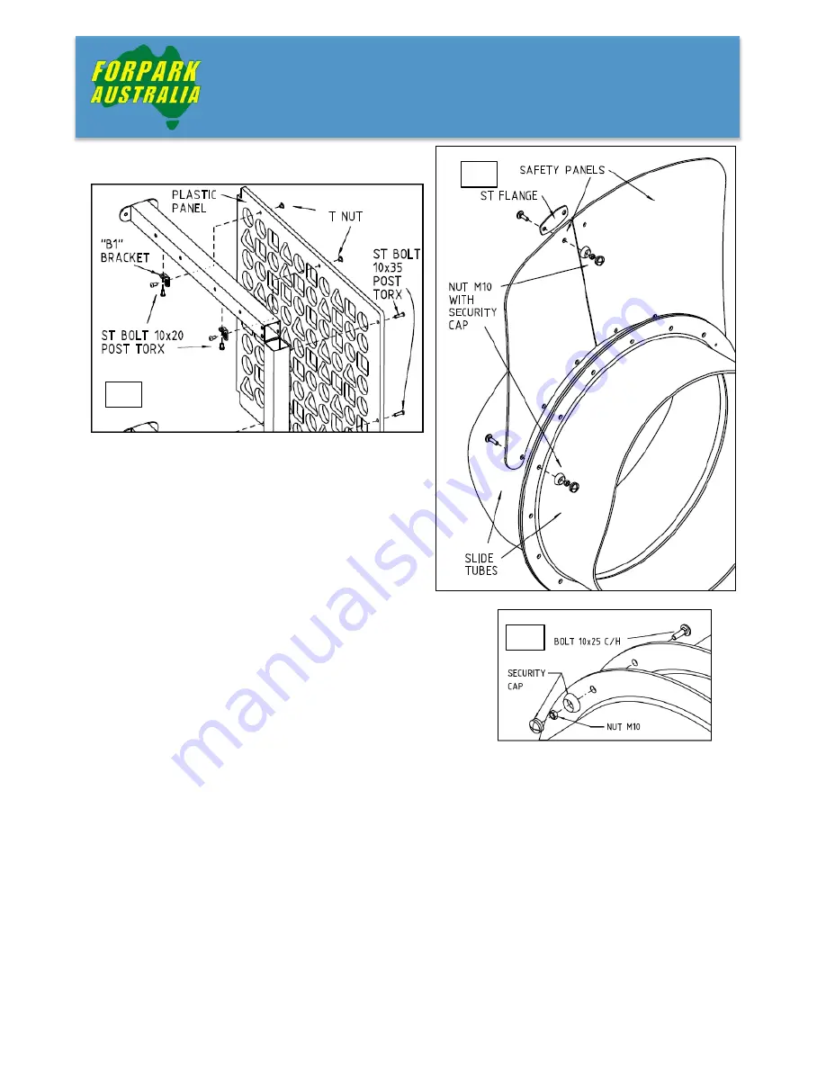
15.


Climb to the first level and assemble according 

to the plan the access to level 2. Do the same for 
level 3. Platform frames need drilling and 
tapping for rope end flanges and plastic panels. 

16.


Build all slides using standard Tunnel slide 
assembly and according to the plan.


The orientation of each tunnel section is 
determined using a process referred to as 
“cranking”.  Cranking consists of placing the 
flanges of both sections together with the seams 
of the section to be attached aligned to the 
seams of the previous section, and rotating it either 
clockwise or anti-clockwise by the required number of bolt 
holes in the flanges.  (For example, 3 cranking steps would 
involve rotating the section by 3 bolt holes.)  Note: 
Clockwise is determined while standing on the ground, 
facing the slide up.


16 

16 

15 

Summary of Contents for Summit

Page 1: ...INSTALLATION MANUAL SUMMIT WWW FORPARKAUST COM AU SUMMIT ...

Page 2: ...st methods AS NZS 4422 2016 Playground surfacing Specifications requirements and test method AS NZS 4685 0 2017 Playgrounds and playground equipment Part 1 Development slide installation inspection maintenance and operation You may be interested to know that Forpark Australia is a family owned Australian company and that we are the largest in house manufacturer of playground equipment in Australia...

Page 3: ...ntents of the crate 2 Securing the site while work is in progress 2 Preparation for installation 2 Reading the Plans 3 Installation 3 Installing Footing Legs 3 Installing Structure 4 Tube Joiner 13 Before Leaving the Site 14 Safety and Maintenance Inspections 14 Routine Visual Inspection 15 Operational Inspection 16 Comprehensive Inspection 17 ...

Page 4: ...e of the soft fall surface and for correct distances between various items of equipment If you are unsure of these requirements you should check with your Forpark representative 4 For ease of installation do not put the soft fall surfacing in until after the equipment has been installed Ensure that you allow for the required soft fall depth when excavating the site Any excavation should take place...

Page 5: ...to set so a barrier or fence will keep people off the equipment until it is ready to be used and until adequate soft fall surfacing has been installed PREPARATION FOR INSTALLATION 1 Before you commence installation you should familiarize yourself with the general instructions of this manual 2 Once ready to commence installation you should lay out the equipment and ensure that you have all items de...

Page 6: ...NG FOOTING LEGS The first stage is to position and concrete legs All legs need to be attached to a frame to be sure the built structure will match all holes on the concreted legs Use the required nuts and bolts to join leg plates to frame plates Use bolt M10x90 for the cross connection at the centre Tighten all parts Lay in correct position and mark ground for the footings Dig holes in the ground ...

Page 7: ...TRUCTURE Remove the jig frame from concreted legs The assembling of the structure columns uprights platform frames platforms walls windows and roof is to be done laying on the ground Follow the steps 1 Use the same jig frame from footing legs raise vertically and attach 2 of the corner pipe columns the same way as the footing legs before Attach the straight columns using 3 plates on every joint Co...

Page 8: ...IA www forparkaust com au 3 Join rings and chains of the access net Access chain net has first and second open rings Check plan for the orientation of the open rings Attach rubber platforms to the platform frame 1 3 3 2 ...

Page 9: ...plan Each platform frame weights 150kg and may need mechanical lifting aid Two legs of the access rail are attached to the access flange and 2 legs to platform frame require drilling and tapping 5 Join the platform frame to the first level uprights that is attached to the columns Continue attaching other platform frames 4 5 ...

Page 10: ...e the floor jig from bottom columns 11 Lift the top of structure with crane to fit the 4 aluminium caps on top columns 12 Raise the structure using the crane by the lugs on the top columns in an upright position and place over the concreted legs The holes on the plates should match as the same jig was used for positioning the legs and bottom columns Bolt all plates together using the same fittings...

Page 11: ...8 FORPARK AUSTRALIA www forparkaust com au 13 Make sure all columns and uprights are vertical well connected and all frames are square 11 15 15 8 ...

Page 12: ... according to the plan The orientation of each tunnel section is determined using a process referred to as cranking Cranking consists of placing the flanges of both sections together with the seams of the section to be attached aligned to the seams of the previous section and rotating it either clockwise or anti clockwise by the required number of bolt holes in the flanges For example 3 cranking s...

Page 13: ...Left 8 Exit Sections 5 and 1 2 Anti clockwise Slide Level 2 Right Spiral Reverse Direction for Slide Left straight sections not shown tube windows facing up Piece Number Description Cranking Steps Direction 2 1st 90o elbow 3 Clockwise 3 2nd 90o elbow 1 Anti clockwise 4 3rd 90o elbows 2 Anti clockwise 5 4th 90o elbow 2 Anti clockwise 6 5th 90o elbow 2 Anti clockwise 7 6th 90o elbow 2 Anti clockwise...

Page 14: ...90o elbow 2 Anti clockwise 11 9th 90o elbow 2 Anti clockwise 12 10th 90o elbow 2 Anti clockwise 13 11th 90o elbow 2 Anti clockwise 14 12th 90o elbow 2 Anti clockwise 15 13th 90o elbow 2 Anti clockwise 16 14th 90o elbow 2 Anti clockwise 18 15th 90o elbow 2 Anti clockwise 20 35o elbow 0 Left 21 Exit Sections 5 and 1 2 Anti clockwise Slide Level 2 Right Curved Reverse Direction for Slide Left straigh...

Page 15: ...i clockwise 11 3rd 90o elbows 3 Clockwise 12 4th 90o elbow 0 Left 13 Exit Sections 6 Anti clockwise 17 Use the crane to lift into position Attach all slides to walls from inside the structure using ST Bolt 10x60 H H into welded nut on tube bracket 18 Attach slide cradle uprights find and dig the holes for the footings Concrete the uprights 19 Mark and dig the holes for the access net bottom anchor...

Page 16: ...ound with standard Forpark uprights footings 1 Build rise and bolt both structures at the correct distance 2 Connect all parts of the Tube Joiner laying on ground 3 Mark and dig the holes in ground for the supporting legs 4 Use crane to lift the Tube Joiner Hold legs spread to right distance to avoid tension and damage on top connections Place legs in holes and bolt flanges to both structure walls...

Page 17: ... safety and maintenance inspections and record the details of your inspections in a logbook In this manner any minor repairs are done as soon as they are required and your equipment will remain in safe condition In the event of an accident occurring on your play equipment your records of these inspections are proof that your duty of care has been maintained We recommend that your play equipment be...

Page 18: ...ee of debris and contamination Check that displacement of your loose fill surfacing material has not resulted in areas becoming shallower than the recommended depth particularly below items of equipment where falls are likely Such areas should be levelled or filled to ensure that the recommended depth is maintained Equipment Check for vandalism and for any damaged or missing parts In the event of ...

Page 19: ...l uprights and components are secure in the ground and that no footings are showing through the soft fall Check steel play equipment for rust or corrosion All metal play equipment will show some signs of breakdown over time and this may be exacerbated by a marine environment Replace any badly corroded parts Check timber equipment for splintering and warping and coat with Sikkens Cetol if required ...

Page 20: ...n playground equipment maintenance or by an engineer Surfacing Equipment In addition to a detailed inspection of all areas covered in an Operational Inspection the following checks should be made Check the structural integrity of equipment subject to corrosion or rotting Check for any changes in the safety of the equipment resulting from repairs made or added or replaced components ...

Page 21: ...forparknsw forparkaust com au Copyright 2018 All designs in this catalogue are copyright and remain the property of Forpark Australia Forpark Australia reserves the right to change designs and colours VIC Unit 24 21 Eugene Tce Ringwood VIC 3134 Ph 03 9870 0233 Fax 03 9870 2079 play safeplay com au NTH QLD PO Box 4873 Cairns QLD 4870 Ph 07 4033 5433 Fax 07 4054 3354 bigsplash pobox com TAS PO Box 1...

Reviews: