background image

Upgrading from an IDD-IIIA

NOTICE:


PM-IDD 9000 Connector / Pin and Label

Left Terminal Block

F

E

D

B

A

12

N/A

11

N/A

10

9

N/A
N/A

7
6

372001-02 Rev L

11

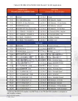
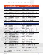
Table 2-3 IDD-IIIA to IDD 9000

AMPLIFIER UPGRADE WIRING TABLES

2.3.1

Summary of Contents for 408100-00

Page 1: ...www forneycorp com BURNERS IGNITERS DAMPERS CONTROLS PM IDD9000 FLAME AMPLIFIER Part 408100 00 Dual Channel Part 408100 50 Single Channel Publication 372001 02 Rev L ...

Page 2: ...PROPRIETARY NOTICE SAFETY ICON DEFINITIONS 372001 02 Rev L i INTRODUCTION DANGER WARNING CAUTION NOTICE ...

Page 3: ...REVISIONS REVISIONS DATE COMMENTS A 02 2009 B 11 2010 06 2011 D 07 2011 E 10 2011 F G H 04 2014 K 01 2017 L 372001 02 Rev L ii ...

Page 4: ...372001 02 Rev Kv TABLE OF CONTENTS ...

Page 5: ...Section 1 General Description Section 2 Installation 372001 02 Rev L iii 1 4 5 6 6 7 7 11 18 18 18 18 19 20 22 23 24 25 26 26 26 27 28 29 31 32 32 32 33 35 36 37 38 38 39 40 40 40 TABLE OF CONTENTS ...

Page 6: ...OF CONTENTS Figure 1 1 Figure 2 1 Figure 2 2 Figure 2 3 Figure 2 4 Figure 2 5 Figure 2 6 Figure 2 7 LIST OF FIGURES Section 4 Maintenance Section 5 RMA Warrant y Section 6 Spare Parts 3 8 18 21 22 23 24 25 41 41 41 42 43 44 45 ...

Page 7: ... 15 16 17 19 20 27 28 30 30 31 45 TABLE OF CONTENTS Table 1 1 Table 2 1 Table 2 2 Table 2 3 Table 2 4 Table 2 5 Table 2 6 Table 2 7 Table 2 8 Table 2 9 Table 2 10 Table 2 11 Table 2 12 Table 2 13 Table 3 1 Table 6 1 LIST OF TABLES ...

Page 8: ...372001 02 Rev L 1 in connectors for ease of maintenance Dual Channel Single Channel SECTION 1 GENERAL DESCRIPTION ...

Page 9: ...372001 02 Rev L 2 output This pulse train then serves as the input to the microprocessor ...

Page 10: ...372001 02 Rev L 3 Figure 1 1 IDD 9000 Block Diagram ...

Page 11: ...CIFICATIONS Models Part 408100 00 Dual Channel Part 408100 50 Single Channel Environmental Extremes Power Requirements Operational Characteristics 3 relays are available for each channel Lamp Main Flame Alarm 1 1 Table 1 1 ...

Page 12: ...372001 02 Rev L 5 Compliant Standards immunity test immunity test EU Directives FM Approved CE CERTIFICATIONS 1 2 ...

Page 13: ...372001 02 Rev L 6 RECOMMENDED TEST TUNING EQUIPMENTAND INSTRUCTIONS 2 1 CAUTION WARNING Description Manufacturer Forney Part Number Forney Forney Forney Table 2 1 Tuning Equipment SECTION 2 INSTALLATION ...

Page 14: ...372001 02 Rev L 7 of this manual MOUNTING CONSIDERATIONS ELECTRICALCONNECTIONS 2 2 2 3 CAUTION Never connect or NOTICE ...

Page 15: ...372001 02 Rev L 8 Figure 2 1 PM IDD 9000 External Connectors ...

Page 16: ...372001 02 Rev L 9 PIN LABEL SIGNAL NAME FUNCTION 1 Hot 2 Neutral 4 Hot Neutral 1 2 4 6 7 1 IDD Detector 2 4 6 7 9 Table 2 2 PM IDD 9000 Pin out Summary ...

Page 17: ...372001 02 Rev L 10 Pin Label Signal Name Function 1 2 4 6 IDD Detector 7 output 9 10 1 Flame 2 4 Lamp 6 7 Alarm 9 1 2 Neutral ...

Page 18: ...g from an IDD IIIA NOTICE PM IDD 9000 Connector Pin and Label Left Terminal Block F E D B A 12 N A 11 N A 10 9 N A N A 7 6 372001 02 Rev L 11 Table 2 3 IDD IIIA to IDD 9000 AMPLIFIER UPGRADE WIRING TABLES 2 3 1 ...

Page 19: ...PM IDD 9000 Connector Pin and Label 4 N A 2 1 N A Right Terminal Block G N A H I N A Note 1 K L 14 16 17 N A Note 1 N A Note 1 19 20 21 Neutral 22 24 N A Note 2 372001 02 Rev L 12 ...

Page 20: ...Upgrading from a PM DR6101E CAUTION 372001 02 Rev L 13 ...

Page 21: ...Table 2 4 PM DR6101E to IDD 9000 Channel 1 for UV 4 Applications PM DR 6101E IDD 9000 Connection Pin and Label Left side Right side Neutral 372001 02 Rev L 14 ...

Page 22: ...Table 2 5 PM DR6101E to PM IDD 9000 Channel 1 for IDD Applications PM DR 6101E IDD 9000 Connection Pin and Label Left side Right side Neutral 372001 02 Rev L 15 ...

Page 23: ...Table 2 6 PM DR6101E to IDD 9000 Channel 2 for UV 4 Applications PM DR 6101E IDD 9000 Connection Pin and Label Left side Right side Neutral 372001 02 Rev L 16 ...

Page 24: ...Table 2 7 PM DR6101E to IDD 9000 Channel 2 for IDD Applications PM DR 6101E IDD 9000 Connection Pin and Label Left side Right side Neutral 372001 02 Rev L 17 ...

Page 25: ...ust then be connected to the cable shield GROUNDING NEWAPPLICATIONS RETROFITTING PM IDD 9000 WITH IDD II IDD IIU OR UV4 DETECTORS RETROFITTING PM IDD 9000 WITH AN IDD ULTRA DETECTOR 2 3 2 1 2 3 2 2 2 3 2 3 372001 02 Rev L 18 Figure 2 2 Grounding PM IDD 9000 NOTICE GROUNDING THE PM IDD 9000 2 3 2 ...

Page 26: ...Table 2 8 PM IDD 9000 LED Indicators This MUST LED STATUS DISPLAYS 2 4 Indicator LED Function Flame Yellow Lamp Yellow Alarm Green Green normally 372001 02 Rev L 19 ...

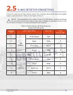
Page 27: ...s and Flame Detectors bottom left side panel FLAME DETECTOR CONNECTIONS 2 5 NOTICE Pin Label Signal Name Wire Color Flame Detector PIN 1 IDD Detector 2 D Green A 4 Black B E 6 Detector 7 D Green A 9 Black B 372001 02 Rev L 20 ...

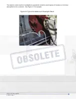
Page 28: ...Figure 2 3 Typical Installation with Sealtight Fitted 372001 02 Rev L 21 ...

Page 29: ...Figure 2 4 IDD Detector Head Wiring 372001 02 Rev L 22 CONNECTING IDD DETECTOR HEADS 2 5 1 ...

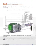
Page 30: ...on each channel Figure 2 5 Wiring one IDD Detector Head to both IDD 9000 Channels NOTICE 372001 02 Rev L 23 CONNECTING ONE IDD DETECTOR HEAD TO BOTH IDD 9000 CHANNELS 2 5 2 ...

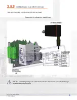
Page 31: ...Figure 2 6 UV 4 Detector Head Wiring NOTICE 372001 02 Rev L 24 CONNECTING UV 4 DETECTOR HEAD 2 5 3 ...

Page 32: ...EITHER OR Figure 2 7 IDD and UV 4 Detector Head Wiring 372001 02 Rev L 25 CONNECTING AN IDD AND A UV 4 2 5 4 ...

Page 33: ...HARDWARE CONTROL INPUTS 2 6 NOTICE BLIND INPUT J8 SENSE B INPUT J8 2 6 1 372001 02 Rev L 26 2 6 2 ...

Page 34: ...372001 02 Rev L 27 OPERATING PROFILE SELECT INPUTS J7 2 6 3 NOTICE J7 pin 1 J7 pin 2 J7 pin 3 ACTIVE PROFILE ...

Page 35: ...NOTE OPERATING MODES 2 7 Mode 1 IDD PPS only Mode 2 UV 4 PPS only IDD GAIN 0 1 1 1 100 0 1 100 0 CHECK DELAY 120 Seconds 372001 02 Rev L 28 ...

Page 36: ...NOTICE CONFIGURING THE TERMIFLEX SMARTDISPLAY TERMINALWITH 25 PIN CONNECTOR 2 8 lower left blue lower right red 372001 02 Rev L 29 ...

Page 37: ...COM DSP KBD COM DSP KBD 372001 02 Rev L 30 ...

Page 38: ...Table 3 1 Keypad Commands NOTE Function Key strokes Terminal Emulator Software TES Button Question mark 372001 02 Rev L 31 SECTION 3 AMPLIFIER TUNING ...

Page 39: ...NOTICE NOTICE MODE 3 1 IDD Channel Tuning IDD Gain 3 1 1 3 1 1 1 372001 02 Rev L 32 ...

Page 40: ...s option Frequency Ranges 3 1 1 2 LEFT RIGHT Gain 1 DEC INC NXT Gain 0 DEC INC NXT Figure 3 2 Incorrect Gain Setting Figure 3 1 Correct Gain Setting F1 F2 F3 F4 F1 F2 F3 F4 F1 F2 F3 F4 IDD Spectrum Ranges 2 CHG NXT 372001 02 Rev L 33 ...

Page 41: ...screen This is the Freq Range s 80 200 x1 1024 1024 x1 CHG1 CHG2 NXT F1 F2 F3 F4 372001 02 Rev L 34 NOTICE Weight Factors Values 1 1 2 2 4 4 6 7 9 ...

Page 42: ... 2 956 100 140 x2 LO HI WF OK F1 F2 F3 F4 F1 F2 F3 F4 F1 F2 F3 F4 372001 02 Rev L 35 point IDD Pick Up and Dropout Points 3 1 1 3 NOTE F1 F2 F3 F4 F1 F2 F3 F4 IDD SIGNAL 956 PU 450 HI 980 DO 300 LO 770 PU DO NXT IDD SIGNAL 956 PU 800 HI 1100 DO 500 LO 560 PU DO NXT ...

Page 43: ...NOTE IDD Analog Output Low and High Points 3 1 1 4 F1 F2 F3 F4 F1 F2 F3 F4 IDD ANALOG OUTS HI 1000 PU 800 LO 0 DO 500 HI LO NXT IDD ANALOG OUTS HI 1100 PU 800 LO 300 DO 500 HI LO NXT 372001 02 Rev L 36 ...

Page 44: ...ultiplier value the Multiplier accept the value Dropout Points Dropout points seen accept the value point NOTE points accept the value most information to almost low to a value lower than the CAUTION critical processes F1 F2 F3 F4 F1 F2 F3 F4 F1 F2 F3 F4 372001 02 Rev L 37 D ...

Page 45: ...e Failure Flame Failure Response Time Delay for Modes 1 and 2 SELF CHECK CYCLE TIME FOR MODES 1 AND 2 3 2 3 3 F1 F2 F3 F4 F1 F2 F3 F4 FFRT 3 8 Seconds CHG NXT Self Check Delay 120 Seconds CHG NXT 372001 02 Rev L 38 ...

Page 46: ...n both Channels If one channel fails at any time for any reason the other channel will continue to operate same time NOTICE NOTICE SAVING CONFIGURATION 3 4 F1 F2 F3 F4 F1 F2 F3 F4 F1 F2 F3 F4 F1 F2 F3 F4 F1 F2 F3 F4 Valid Range 30 600 0 OK Self Check Delay 300 Seconds CHG NXT RESTORE OR SAVE 860 PPS UV LOAD SAVE SELF OLD NEW CHK PPS CHK FAIL PPS CHK FAIL PPS CHK FAIL 860 PPS UV Set 0 372001 02 Rev...

Page 47: ...CAUTION FUNCTIONS UNAVAILABLE WHILE TUNING ANALOG OUTPUTS AMPLIFIER SHUTDOWN FAILURE 3 5 3 6 3 7 372001 02 Rev L 40 ...

Page 48: ...This section contains maintenance instructions for the PM IDD 9000 CAUTION WARNING TUNING TROUBLESHOOTING 4 1 4 2 maintain optimum system performance 372001 02 Rev L 41 SECTION 4 MAINTENANCE ...

Page 49: ...STORAGE AND HANDLING REQUIREMENTS 4 3 372001 02 Rev L 42 ...

Page 50: ...SECTION 5 RMA WARRANTY 372001 02 Rev L 43 ...

Page 51: ...SECTION 6 SPARE PARTS Email Phone Fax 372001 02 Rev L 44 372001 02 Rev L 44 ...

Page 52: ...RECOMMENDED SPARE PARTS 6 1 NOTE Fuse Value Function Part No F1 2 0A F2 IDD Detector Power F4 F6 62mA IDD Bias Table 6 1 Replacement Parts 372001 02 Rev L 45 ...

Page 53: ...B Sense A Sense B IDD GAIN FREQ RANGES CORNER 1 CORNER 2 CORNER 3 CORNER 4 WEIGHT 1 WEIGHT 2 IDD PICKUP PPS IDD DROPOUT PPS IDD ANALOG LOW PPS IDD ANALOG HIGH PPS MODE 2 UV 4 MULTIPLIER UV 4 PICKUP PPS UV 4 DROPOUT PPS UV 4 ANALOG LOW PPS UV 4 ANALOG HIGH PPS MODES 1 2 FFRT CHECK DELAY 372001 02 Rev L 46 ...

Reviews: