

4-15
FORMULA
CONTROLS AND INDICATORS
SUN SPORT
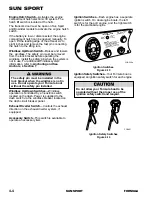
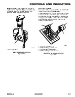
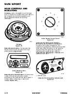
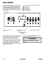
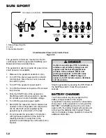
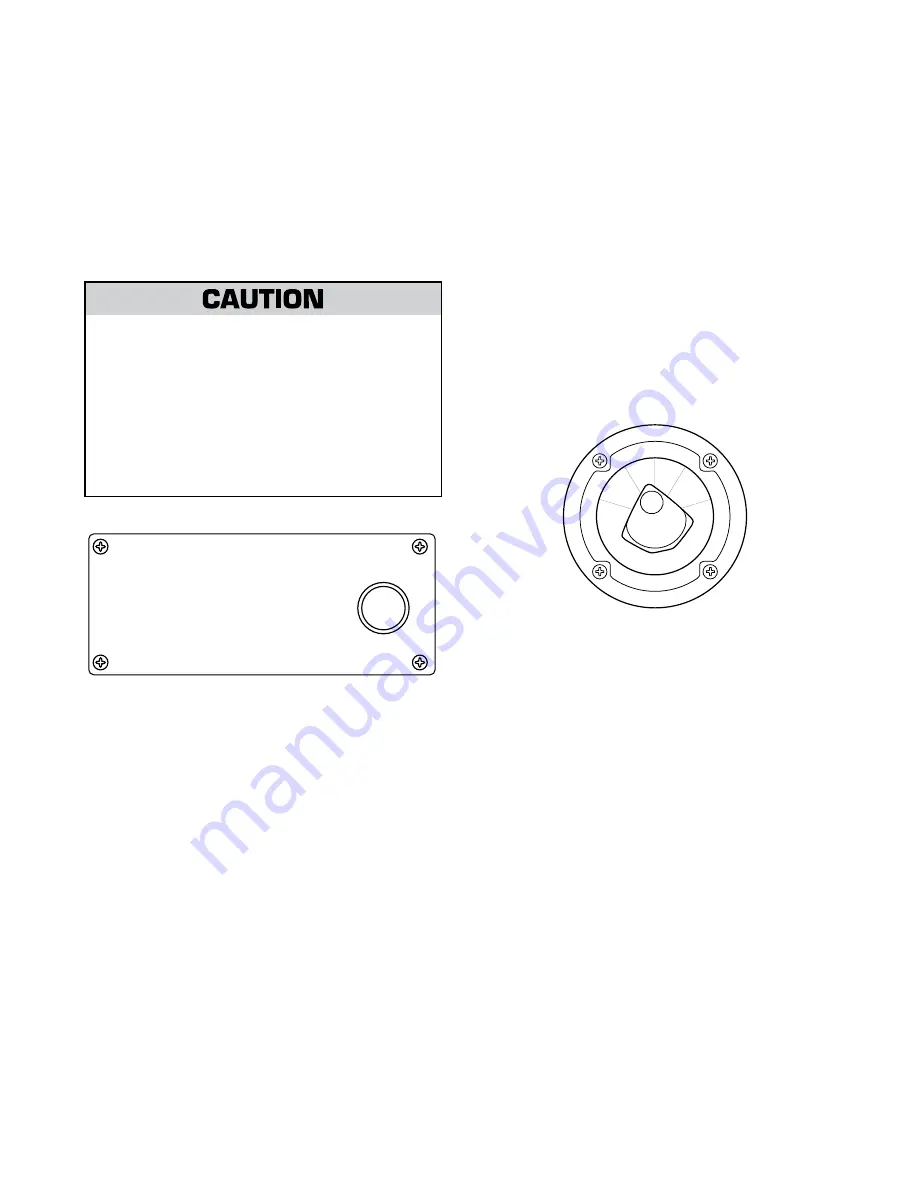
Macerator Control
—Controls operation of the
macerator waste system. Your Formula boat may
be equipped with a macerator system that allows
the discharging of waste water directly overboard
through a seacock. The macerator control is
located in the head compartment. The macerator
overboard Y-valve must be opened to allow
activation of the macerator pump switch. For
additional operating information, refer to the
macerator operator’s manual.
Overboard di
s
charge of wa
s
te water
s
hould only be u
s
ed in approved area
s
. It
i
s
your re
s
pon
s
ibility to comply with local
regulation
s
regarding the di
s
charge of
wa
s
te. You could be fined if your boat ha
s
an operable overboard di
s
charge
s
y
s
tem
in a non-approved area. Removing the
handle of the
s
eacock while in a clo
s
ed
po
s
ition, or di
s
abling the
s
y
s
tem by other
mean
s
may be required to avoid a fine.
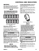
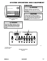
BATTERY SELECTOR
SWITCHES
Your Formula boat is equipped with a battery
switch for each engine. The switch provides
isolation and positive disconnect of the battery to
protect against tampering, electrical fire hazards
and draining the battery’s power. The battery
switch used in each Formula boat is dependent
upon model and engine options.
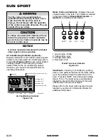
Macerator Control Panel
Figure 4-35
MACERATOR
CAUTION: BEFORE OPERATING MACERATOR;
1. SWITCH Y-VALVE TO DIRECT FLOW TO MACERATOR
2. OPEN SEACOCK
3. PRESS AND HOLD SWITCH TO DISCHARGE WASTE
4. RELEASE SWITCH WHEN WASTE IS DISCHARGED
5. CLOSE SEACOCK
NOTICE:
COAST GUARD REGULATIONS DO NOT ALLOW DISCHARGING
OF NON-TREATED WASTE IN FRESH WATER BODIES OR
IN SALT WATER BODIES, WITHIN THREE MILES OF SHORE.
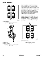
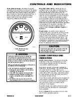
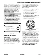
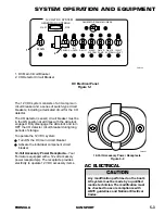
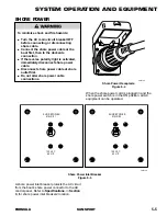
Typical Single Engine Battery Switch
—This
battery switch
(Figure 4-36)
connects one or two
batteries to the electrical circuit of an engine.
Rotate the switch to:
•
No. 1 position – Power supplied to engine and
12 VDC system from battery 1 (engine
alternator recharges battery 1).
•
No. 2 position – Power supplied to engine and
12 VDC system from battery 2 (engine
alternator recharges battery 2).
•
ALL position – Power supplied to engine and
12 VDC system from batteries 1 and 2 (engine
alternator recharges batteries 1 and 2).
•
OFF position – Neither the engine or 12 VDC
system is supplied with power.
Note:
Power is supplied to the bilge pumps, high
water alarm, stereo memory, and galvanic
protection system through the constant power
circuit, independent of the battery switch position
(i.e., these components receive power even with
the battery switch in the OFF position).
Formula recommends starting your engine with
the battery switch in the ALL position. This will
supply your engine with the most cranking power
as well as charge both batteries while the engine
is running. If you intend to use 12 VDC accessory
power for an extended period of time without the
engine running, switch to only one battery.
For the location of the battery selector switch,
refer to
Specifications
, in
Section 3
.
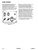
Typical Battery Selector Switch
Figure 4-36
1
ALL
2
O
F
F
S
T
O
P
E
N
G
IN
E
S
BEFO
RE
S
WIT
CH
IN
G
"O
F
F
"
KC 1642
FOR222
KC-1642
Summary of Contents for SUN SPORT
Page 20: ...2 12 FORMULA SUN SPORT SUN SPORT...
Page 22: ...3 2 FORMULA SUN SPORT SUN SPORT DIMENSIONS FOR218A F E C B D A FOR218A...
Page 42: ...3 22 FORMULA SUN SPORT SUN SPORT...
Page 120: ...9 8 FORMULA SUN SPORT SUN SPORT...
Page 124: ...10 4 FORMULA SUN SPORT SUN SPORT...
Page 128: ...11 4 FORMULA SUN SPORT SUN SPORT...
Page 132: ...12 4 FORMULA SUN SPORT SUN SPORT...
Page 134: ...13 2 FORMULA SUN SPORT SUN SPORT FUEL LOG Date Gallons Date Gallons Date Gallons Date Gallons...
Page 138: ...13 6 FORMULA SUN SPORT SUN SPORT...


