


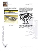


WASTE WATER SYSTEM
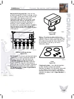
Waste water from the bilge pump(s) and sump
tank is directed to a waste water manifold. The
waste water manifold handle must be in the
open position for the waste water to discharge
through the hull fitting. Refer to
Specifications
,
in
Section 3
, for waste water manifold(s)
location(s).
1. Handle in Open Position
HEAD SYSTEM OPERATION
Your Formula Yacht is equipped with a
Sealand
Vacuflush Head System
.
For an in-depth description of the operation and
maintenance procedures for the head system
specific to your boat, refer to the manufacturer’s
literature located in the “Systems” section of the
Formula Owner Information Binder. The following
general information provides the basics of this
system’s operation.
Waste Water Manifold
Figure 5-16
1
5-14
Section 5
Electric VacuFlush Head
—The VacuFlush
system is active when the 12V DC system is
energized and the HEAD PUMP circuit breaker
is turned ON. The head pump creates a vacuum
in the waste system. When the toilet is flushed,
this stored vacuum clears the bowl of waste. The
vacuum pump will run for a few minutes after
flushing to restore vacuum in the system and
then automatically shut off upon reaching the set
vacuum level.
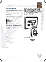
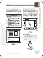
The Electric VacuFlush Head is controlled via a
remote switch. When the GREEN light is
illuminated, it is safe to flush the toilet. To do this,
momentarily press the bottom portion of the
rocker switch. If it is necessary to add water to
the bowl, press the top portion of the rocker
switch. Do not attempt to flush the toilet if the
RED light is illuminated.
VacuFlush Head Remote Switch
Figure 5-17
The water pump breaker on the 12V DC panel
must be turned ON (not necessary if boat is
connected to dockside water supply). This
provides the water needed for flushing.
Monitor your waste tank level indicator to know
when your tank has reached its full level and it’s
time to have it pumped out.
FOR
33
0
FOR082
Summary of Contents for 48 2008
Page 28: ...NOTES 3 8 Section 3...
Page 70: ...NOTES 5 28 Section 5...
Page 82: ...Close Quarter Turns Figure 7 4 TWIN ENGINE MANEUVERING 7 6 Section 7 KC 1521...
Page 118: ...NOTES 10 4 Section 10...
Page 122: ...NOTES 11 4 Section 11...
Page 126: ...NOTES 12 4 Section 12...
Page 127: ...13 1 SERVICE LOG Date Hour Reading Service Repairs Performed Section 13 Forms...
Page 128: ...FUEL LOG Date Gallons Date Gallons Date Gallons Date Gallons 13 2 Section 13...
Page 132: ...NOTES 13 6 Section 13...


