background image

18

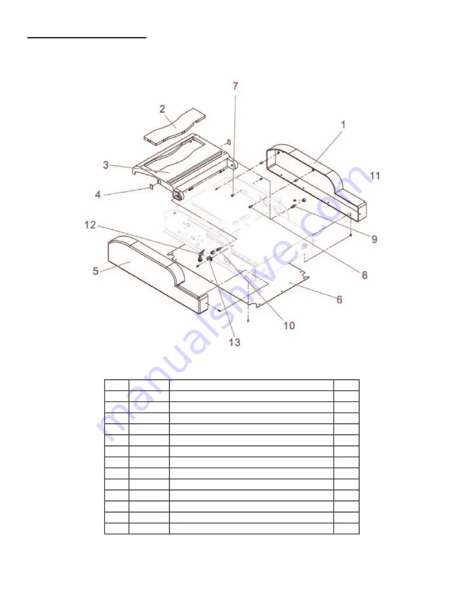
EXTERIOR SECTION

ITEM

PART

DESCRIPTION

QTY. 

1

COVER B

1

2

BMT 21

ACRYLIC COVER

1

3

BMT 22

TOP COVER

1

4

MAGNETIC

2

5

COVER F

1

6

BASE PLATE

1

7

COVER STOPPER

2

8

COVER SCREW

2

9

PILLAR

1

10

PILLAR

1

11

COLLAR

2

12

TOP COVER SWITCH ASSEMBLY

1

13

BRACKET

1

Summary of Contents for FD 180

Page 1: ...FD 180 Booklet Maker OPERATOR MAINTENANCE MANUAL MAINTENANCE MANUAL MAINTENANCE MANUAL FIRST EDITION 11 2009 ...

Page 2: ......

Page 3: ...N STANDARD PAPER SIZE 5 RECALLING A PAPER SIZE FROM MEMORY 5 SETTING THE STAPLE TRIGGER TIMING 6 RESETTING FACTORY DEFAULTS 6 MAKING BOOKLETS 7 CORRECTING STAPLE MISALIGNMENT 8 CORRECTING FOLD MISALIGNMENT 9 COUNTER RESET 10 EMERGENCY STOP 10 CLEARING JAMMED STAPLES 10 SERIAL INDICATOR 10 TROUBLESHOOTING 11 DAILY MAINTENANCE 11 PARTS LIST 12 ...

Page 4: ......

Page 5: ...0 17 L x 8 25 12 W Speed Up to 500 booklets per hour operator dependent Stapling Heads Two automatic stapling heads with five stapling positions Dimensions 22 L x 17 25 W x 6 5 H Weight 60 lbs Voltage 110 Volts AC 60Hz FUNCTION The Formax FD 180 Automatic Booklet Maker offers an easy to use solution for creating booklets in small run or in plant applications It s lightweight portable and sets up in...

Page 6: ...ler head 3 Open the cassette from the stapler head and load staples fig 2 4 Move the stapler heads to the correct posi tion to match paper size Refer to stapler head position sticker fig 3 on the underside of the top cover 5 Close the top cover and plug power cord into receptacle on back of unit and into appropri ate wall receptacle fig 4 Fig 1 Fig 2 Fig 3 ...

Page 7: ...ithin Options Menu 4 Scroll Down Button Decrease standard paper size Select options within Menu Decrease size of non standard paper within Options Menu 5 Enter Button Accept a revised paper setting Confirm the setting is complete Return to standby mode 3 SAFETY GUIDELINES When machine is running keep hands away from the rollers Do not remove any covers The machine contains high voltage parts and ha...

Page 8: ...each the correct size Then press Enter button to confirm paper size LD LEDGER 11 X 17 LG LEGAL 8 1 2 X 14 LT LETTER 8 1 2 X 11 3 Open top cover Move the stapler heads to the correct position fig 5 by following the stapler head position sticker Close top cover 4 Press the Enter button to return to ready STANDARD PAPER SIZE SELECTION Fig 5 4 ...

Page 9: ...example 14 in SELECTING NON STANDARD PAPER SIZE 5 Press Enter button to input the data to the selected Memory location and return to ready status RECALLING A PAPER SIZE FROM MEMORY 1 To recall a paper size saved in Memory press the scroll up or down button until you reach the correct size example M3 2 Press Enter button to confirm chosen size 3 Open top cover Move the stapler heads to the correct p...

Page 10: ...he setting example 8 seconds 5 Press the Enter button to rewrite the previous value and return to ready RESETTING FACTORY DEFAULTS 1 Press the Menu button to enter Option Menu 2 Select 5 Reset All by pressing the scroll down button 3 Press Enter button to reset all data to factory default settings WARNING All the values in Memory will be restored to the factory default value 297mm 4 Press Enter bu...

Page 11: ...aper with the edge of the scale fig 6 3 Place the paper side guide by aligning it with the edge of the paper fig 7 4 Use the cylindrical magnetic alignment stop pers if needed fig 8 Fig 6 Fig 7 Fig 8 Fig 9 5 Close the top cover The machine will start operation in 5 seconds Once the first booklet is complete remove it from the output slot on the top Insert the next set of sheets fig 9 and continue opera...

Page 12: ...nter line of the booklet 2 Check to see if the staples align with the center line 3 Fine adjustments to staple position can be made by following the in structions below Repeat until staples and center line are aligned CORRECTING STAPLING MISALIGNMENT 8 ...

Page 13: ...osition by aligning with the center line 2 Fine adjustments to fold position can be made by following the instructions below Repeat until center line and fold are aligned CORRECTING FOLDING MISALIGNMENT Fold position 9 ...

Page 14: ...emove all paper from the machine 2 Press Enter button to reset the counter to 0000 1 Press any button on the control panel to stop the machine during the booklet making process 2 Switch off the machine then power on the machine to return to ready status 1 Open the top cover and lift up the stapler head lever 2 Open the cassette from the stapler head and remove the jammed staple using tweezers EMER...

Page 15: ...per Turn off power for 3 seconds Turn on power to return to ready status One of the control panel keys has been pressed during booklet making process Turn off power for 3 seconds then turn on to return to ready status DAILY MAINTENANCE TROUBLESHOOTING Be sure to turn off power before cleaning Use a soft clean cloth dampened with alcohol or neutral detergent The folding rollers may cause paper slip...

Page 16: ...EMBLY UNIT BASE ASSEMBLY 1 1 1 SCALE 1 1 2 PLATE 1 2 ANVIL 5 3 FRAME F 1 4 CONTROL PANEL 1 5 PANEL P W B UNIT 1 6 ACRYLIC PLATE 1 7 PANEL BRACKET 2 8 SCREW 4 9 BMT 29 RUBBER FOOT 4 10 PAPER SIDE GUIDE 1 11 MAGNETIC STOPPER 1 12 MAGNETIC STOPPER 1 13 FRAME B 1 ...

Page 17: ...CRIPTION QTY 1 ASSEMBLY UNIT GUIDE BLOCK ASSEMBLY 1 1 1 GUIDE BLOCK 1 1 2 COLLAR 1 1 3 ANGLE 1 1 4 TIMING BELT 1 1 5 PLATE 1 2 SHAFT 1 3 COLLAR 1 4 ANGLE 1 5 GEAR 1 6 GEAR 1 7 STUD 1 8 SIDE GUIDE 1 9 BALL RETAINER 2 10 BMT 26 STEP MOTOR 1 ...

Page 18: ... FOLDING BLADE SECTION ITEM PART DESCRIPTION QTY 1 SHAFT 1 2 HOLDER 2 3 COLLAR 2 4 KEY 1 5 CAM F 1 6 BMT 30 BEARING 3 7 FOLDING BLADE 1 8 SHAFT 1 9 COLLAR 2 10 SPRING T 2 11 LEVER F 1 12 BMT 20 LEVER B 1 ...

Page 19: ...LY UNIT BMT 31 STAPLE ASSEMBLY 1 1 1 LEVER F 1 1 2 LEVER B 1 1 3 4 1 4 STAPLER HEAD COVER 2 1 5 BALL RETAINER 2 2 STAPLER HEAD 2 3 PRESS ROLLER HEAD 1 4 BMT 1 BEARING 1 5 COLLAR 2 6 BMT 16 SENSOR HOLDER R 1 7 BMT 17 SENSOR HOLDER L 1 8 BLOCK 1 9 SPRING T 1 ...

Page 20: ...ECTION ITEM PART DESCRIPTION QTY 1 PLATE ASSEMBLY 1 2 PLATE 1 3 BMT 27 MOTOR 110V 1 4 BLOCK 1 5 SPRING T 1 6 SPROCKET IV 3 7 MOTOR SPROCKET 1 8 CHAIN 1 9 SPROCKET 1 10 CHAIN 1 11 KEY 1 12 BMT 19 SPROCKET ASSEMBLY 1 ...

Page 21: ...17 FOLDING SECTION ITEM PART DESCRIPTION QTY 1 ASSEMBLY UNIT ROLLER ASSEMBLY 2 1 1 ROLLER 1 1 2 SQUARE METAL 1 1 3 SPROCKET IV 1 2 2 3 SQUARE METAL 2 4 SPRING C 4 ...

Page 22: ...RT DESCRIPTION QTY 1 COVER B 1 2 BMT 21 ACRYLIC COVER 1 3 BMT 22 TOP COVER 1 4 MAGNETIC 2 5 COVER F 1 6 BASE PLATE 1 7 COVER STOPPER 2 8 COVER SCREW 2 9 PILLAR 1 10 PILLAR 1 11 COLLAR 2 12 TOP COVER SWITCH ASSEMBLY 1 13 BRACKET 1 ...

Page 23: ...SECTION 1 ITEM PART DESCRIPTION QTY 1 SENSOR BRACKET 1 2 SENSOR ASSEMBLY 1 3 MAIN BOARD BRACKET 1 4 TRANSFORMER 110V 1 5 MOTOR CAPACITOR 110V 1 6 MAIN POWER SWITCH 1 7 FUSE HOLDER 1 8 FUSE 1 9 INLET 1 10 POWER CORD 1 ...

Page 24: ...N QTY 1 BMT 23 MAIN P W B 1 2 BUNDLE WIRE 1 3 BUNDLE WIRE 8P 1 4 BUNDLE WIRE 4P 1 5 BUNDLE WIRE 3P 1 6 BUNDLE WIRE 8P 1 7 BUNDLE WIRE 20P 1 8 BUNDLE WIRE 2P 1 9 BMT 24 POWER SUPPLY UNIT 110V 1 10 COLLAR 1 11 BOARD SPACER 1 12 MAIN BOARD BRACKET 1 ...

Page 25: ...21 ELECTRICAL SECTION 3 ...

Reviews:

Related manuals for FD 180