

MV-1620HSA
Quick Setup Guide
Use SDI or HDMI monitors that
support 1920 x 1080 (59.94 or 50)
interlaced or progressive video
signals, or 1280 x 720 (59.94 or 50)
progressive video signals.
Packing list: MV-1620HSA (1), Quick Setup Guide (1), CD (Installation CD 1
including Operation Manuals), AC cord (1), AC cord retaining clip (1 set), Rack
mount bracket set (1 set), Rubber feet
Option items: (installed before shipment) MV-1620PS (including AC cord and
AC cord retaining clip), MV-1620IF, MV-1620DO, MV-1620SNMP, MV-1620RT
(Included with unit) Breakout cable (PC3323-1)
Front Panel
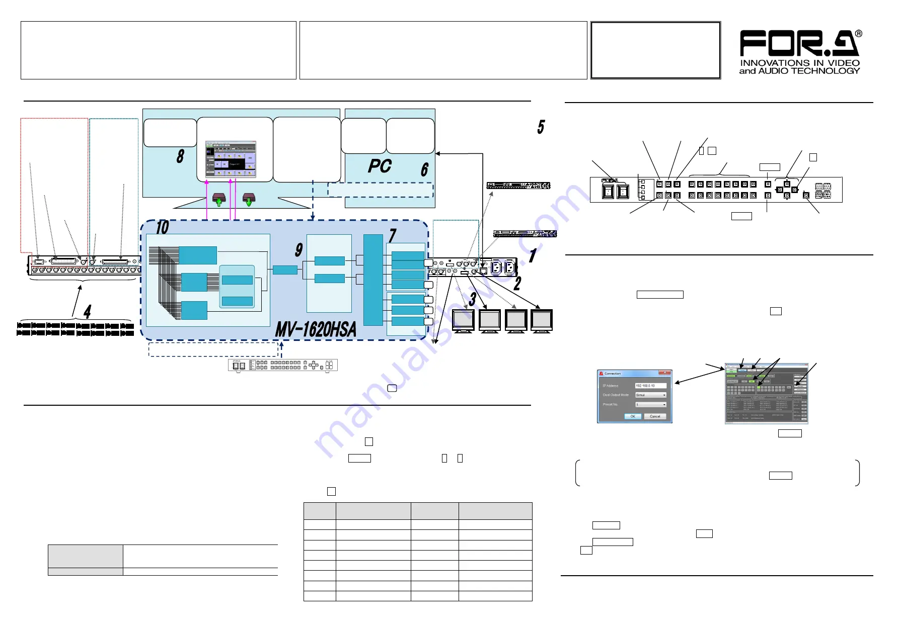
The procedure is shown numbered in the above figure.
1
Apply DC power to the MV-1620HSA using the supplied AC cord.
Secure the cord with the supplied AC cord retaining clip.
Ground the unit for your safety.
2
Connect an HD-SDI monitor.
3
Connect an HDMI monitor.
4
Connect signal source devices, such as video cameras, to the
HD/SD-SDI INPUT and/or COMPOSITE INPUT connectors.
5
Connect a PC to be used for remote control to the MV-1620HSA LAN
connector using a LAN cable.
6
Change the
PC
network settings for the connection with the
MV-1620HSA.
Go to
Local Area Connection
>
General
>
Internet Protocol (TCP/IP)
>
General
>
Properties
, then set the IP address and Subnet mask to match that
of the MV-1620HSA.
PC IP address
192.168.0.yyy (yyy is any number from 1 to 254
except for the number set for the MV-1620HSA
unit and gateway number. )
Subnet mask
Set to 255.255.255.0.
* The MV-1620HSA IP address can be changed via the MV-1620HSA main
unit menu or Remote Controller (supplied software). 192.168.0.10 is the
default IP address.
7
Verify outputs to the SDI monitor, HDMI monitor and audio devices
using test signals. (The default output is Output 1. To change the
output, use the (1) OUT1/OUT2 button on the front panel.)
1) Hold down the
→
button for it to flash, so that a test signal is
output.
2) Press the SHIFT button, then buttons 1 to 8 light sequentially
allowing you to select a format. (1 is the default format in the
below table.)
3) To exit HDMI/SDI/AUDIO test signal selection mode, hold down
the
→
button for it to go off.
Button
HDMI
SDI
AUDIO
(HDMI/SDI/Analog)
1
720x480p 59.94 Hz
1080/59.94i
1kHz Tone
2
720x576p 50 Hz
1080/50i
1kHz Tone
3
1920x1080p 59.94 Hz
1080/59.94p
1kHz Tone
4
1920x1080p 50 Hz
1080/50p
1kHz Tone
5
1920x1080i 59.94 Hz
1080/59.94i
1kHz Tone
6
1920x1080i 50 Hz
1080/50i
1kHz Tone
7
1280x720 59.94 Hz
720/59.94p
1kHz Tone
8
1280x720 50 Hz
720/50p
1kHz Tone
8
Install Layout Manager (Remote Controller, Layout Editor, Logo Registry) from the
supplied CD.
1) Install the software, then go to
Start
>
All Programs
>
FOR-A
>
MV-1620HS
>
MV-1620HS Layout Manager
to start the program.
2) Press the (8) Online/Offline button under the menu bar in the main window.
3) The connection dialog appears. Enter the MV-1620HSA IP address, (select a Dual
Output mode*) and select 1 for Preset No., then click OK.
* Dual Output offers 2 operation modes; Simul mode: Outputs 1 and 2 are paired and a
layout or a pair of layouts for 2 screens are controlled as one; Independent mode:
Layouts of 2 outputs are controlled separately.
* If the connection cannot be established, check the LAN connection and the PC
network settings.
4) If you wish to use Hangul (Korean characters), click the Layout button
(9)
in the
Layout Manager window to open the Layout Edito
r
page, then select
Settings >
Encode > EUC-KR
from the menu bar in the Layout Editor page.
9
If you are using a monitor other than
SDI:
1080/59.94i or
HDMI:
1080/59.94p, set
frequency and Interlaced/Progressive settings. Click the Layout button
(9)
in the
Layout Manager window to open the Layout Editor page.
1) From the menu bar, go to
Settings
>
System
. In the System page, go to the
System
tab >
General
tab, then set Frequency and Interlaced/Progressive settings.
10
Select
SDI/COMPOSITE
for the signal input.
Input signals must be displayed in windows in the 16-split (default) screen. If not, click
the Remote button (10-
①
in the above figure) in the Layout Manager window to open the
Remote Controller page. Click the Multi button and the Preset (layout) #1 (
10-
②
). Click
the Input Select button (
10-
③
) to open the Input Select dialog. Select the input, then click
OK.
Check to see if the monitor has been properly connected. If nothing still appears on the
monitor, check the monitor
’s specification sheet to see if the monitor supports any of the
formats listed in the left table.
If Nothing Appears on the Monitor!
Power switch
Status
lamps
(2) FULL/MULTI
Full screen/Multi-channel
screen selection button
Hold down to output Editor
output screen.
(3) WINDOW
Turns window
selection mode
ON/OFF.
(4) SOURCE
Turns input source selection mode ON/OFF.(Lit: ON
)
Hold down to turn SDI/COMPOSITE selection mode.
(Flashing: SDI/COMPOSITE selection is enabled.)
Initiates auto
sequence.
(1) OUT1/OUT2
Switches outputs.
Audio mode
selection
button
1~16: Used to select layouts and
source channels.
SHIFT
MENU button
Hold down
:
Opens menu
Press
:
Returns to the
upper layer menu.
Arrow buttons
Locks front panel
buttons.
ON
O FF
POW ER 1
POW ER 2
PO WER 1
PO WER 2
F AN
ALA RM
GE NLO CK
FU LL
MULT I
AUT O
WINDOW
OUT 1
OUT 2
SOU RCE
AU DIO
1
2
9
10
3
11
4
12
5
13
6
14
7
8
15
16
SHIFT
MENU
LO CK
EN T ER
MV-1620 HS
MU L T I V I E W E R
→
button
Hold down to
output test signals.
Click (8)
↓
Connection
dialog opens
(8)
(9)
(10-
①
)
(10-
②
)
(10-
③
)
Connection and System Configuration
Setup Procedure
‚Q
‚P
HD-SDI/SD-SDI/COMPOSITE INPUT
AC100-240V 50/60HzIN
SER. NO.
LAN
HD-SDI OUT1
BKGD VIDEO
IN
OUT
HD-SDI OUT2
HDMI OUT1
L
R
HDMI OUT2
AUDIO OUT2
L
R
AUDIO OUT1
16
15
14
13
12
11
ANALOG / DIGITAL AUDIO IN
10
9
8
7
6
REF IN
LTC IN
REMOTE / TALLY
5
4
3
2
1
RS-232C / 422 / 485
‚Q
‚P
HD-SDI/SD-SDI/COMPOSITE INPUT
AC100-240V 50/60HzIN
SER. NO.
LAN
HD-SDI OUT1
BKGD VIDEO
IN
OUT
HD-SDI OUT2
HDMI OUT1
L
R
HDMI OUT2
AUDIO OUT2
L
R
AUDIO OUT1
16
15
14
13
12
11
ANALOG / DIGITAL AUDIO IN
10
9
8
7
6
REF IN
LTC IN
REMOTE / TALLY
5
4
3
2
1
RS-232C / 422 / 485
LAN
:
Connect a PC to run the
supplied software programs.
(Also for connections with
switchers, etc., when an IF
option is installed.)
Remote Controller
(To control inputs
and outputs)
Layout Editor
(To create/edit layouts)
Upload/Download
Live Viewer
(To output
video signal
to PC)
Web Browser
(To view the
output video
on PC)
Logo Registry
(To edit/save
logos)
Remote Controller control range
3G/HD/SD-SDI/COMPOSITE INPUT
(Connect video cameras, switchers,
etc, to input video signals.)
LTC IN
(Input a time
code.)
REMOTE/TALLY
(GPIO for tally
and layout
control.)
RS-232C/422/485
(Connect a PC for
remote control.)
IF option
REF IN
(Input an
external
reference
signal.)
ANALOG/DIGI
TAL AUDIO IN
(Input analog
or digital audio
signals from
VTR and/or
switcher.)
DO option
HDMI OUT1, 2
(Connect
1080/59.94p
monitor.)
HD-SDI OUT1, 2
(Connect
1080/59.94i
monitor.)
AUDIO OUT1, 2
(Connect audio
device for analog
audio signals.)
‚Q
‚P
HD-SDI/SD-SDI/COMPOSITE INPUT
AC100-240V 50/60HzIN
SER. NO.
LAN
HD-SDI OUT1
BKGD VIDEO
IN
OUT
HD-SDI OUT2
HDMI OUT1
L
R
HDMI OUT2
AUDIO OUT2
L
R
AUDIO OUT1
16
15
14
13
12
11
ANALOG / DIGITAL AUDIO IN
10
9
8
7
6
REF IN
LTC IN
REMOTE / TALLY
5
4
3
2
1
RS-232C / 422 / 485
‚Q
‚P
HD-SDI/SD-SDI/COMPOSITE INPUT
AC100-240V 50/60HzIN
SER. NO.
LAN
HD-SDI OUT1
BKGD VIDEO
IN
OUT
HD-SDI OUT2
HDMI OUT1
L
R
HDMI OUT2
AUDIO OUT2
L
R
AUDIO OUT1
16
15
14
13
12
11
ANALOG / DIGITAL AUDIO IN
10
9
8
7
6
REF IN
LTC IN
REMOTE / TALLY
5
4
3
2
1
RS-232C / 422 / 485
BKGD VIDEO OUT
(Cascade connection
output. Connect to
MV-1620DO BKGD IN)
BKGD VIDEO IN
(Cascade connection
input. Connect to
MV-1620DO BKGD OUT)
DO option
OP
OUT 2 is supported by the MV-1620DO option.
-
。
Audio outputs
Video outputs
MV-1620HSA front panel control range
For layouts of
1920x1080
Interlaced /
Progressive
selection
HDMI
I / P
HD-SDI
I / P
HDMI OUT 1
HDMI OUT 2
HD-SDI OUT 1
HD-SDI OUT 2
Test
signal
output
HDMI
/SDI
/AUDIO
HD-SDI
OUT 1, 2
HDMI
OUT 1
,
2
Analog OUT1, 2
OP
OP
OP
OP
OP
Layout
.
.
.
.
Layout 1
Layout 16
Input source 1 - 16
Full screen
Multi-ch
screen
Editor output
screen
Frequency


