background image

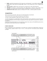
4.

MODE

: operating mode selector for the power amp inputs/outputs. It is possible to select between

parallel  (PAR),  stereo  (STR)  and  bridge  (BRD)  mode.  For  more  information,  see  the  CONNECTION
section.

5.

LINK CH1-CH4

: unbalanced line level outputs for channels CH1 to CH4, RCA connectors.

6.

GROUND

:  this  selector  is  normally  placed  in  the  GND  position.  If  there  are  mass  noises  in  the

installation, move the selector to the LIFT position to separate the mass from the system earth.

7.

OUTPUT CH1–CH4

: speaker outputs for channels CH1 to CH4, 4-contact speakon connectors.

CONNECTION

-Before making any connection, make sure that all the equipment is switched off.

-Check that the CH1 to CH4 volume controls are at their minimum.

-Connect a mixer/preamplifier stereo output to inputs CH1 to CH4.

-Connect the speakers in a series/parallel circuit so that the speaker charge impedance is equal to the power
amp output impedance and that the power supplied by the power amp does not exceed what is stood by
the speakers.

Depending on the desired application, three operating modes can be chosen with the MODE selector on the
back panel: parallel mode, stereo mode or bridge mode.

STEREO MODE (STR)

Move the MODE selector to the STR position. In this mode, the 4 channels work independently. Connect the
4 inputs and the 4 speaker outputs to pins 1+ and 1- on the connector. The channel volume is adjusted
separately.

- 5 -

EN

Summary of Contents for SA-4150

Page 1: ...SA 4150 MULTICHANNEL POWER AMPLIFIER EN Instruction manual...

Page 2: ...o allow ventilation Avoid direct sunlight heat sources and excessive dust Do not place the machine near magnetic elds or static electricity Do not use surfaces which vibrate or receive impact Do not p...

Page 3: ...a dealer when purchasing a similar product at no additional cost It also shows that the machine was put on the market after 13th August 2005 European Community Directive 2002 96 CE of Electrical and E...

Page 4: ...ion circuits is activated switch the system off correct the problem that caused it to be activated and then leave the equipment a few minutes before switching on again 3 LIMIT LED peak indicators that...

Page 5: ...n make sure that all the equipment is switched off Check that the CH1 to CH4 volume controls are at their minimum Connect a mixer preampli er stereo output to inputs CH1 to CH4 Connect the speakers in...

Page 6: ...to the BRD position In this mode the CH1 and CH2 input is the CH1 input signal and the two channels connect internally so that the power is joined to make just one output The CH1 output must be used...

Page 7: ...rature and DC INDICATORS LED signal protection and peak indicator per channel INPUTS 4 auxiliary line inputs combo XLR and 6 3 mm stereo jack 0 775V at 4 OUTPUTS 4 RCA 0 775 V at 4 RESPONSE 20 20 000...

Page 8: ...liquids or other substances excessive humidity battery deterioration and internal manipulation of the device the software or its components by unauthorized persons and in general any use that is unrel...

Reviews: