EN
- 3 -
BACK PANEL
1 2 3 4
1
2
3
1 2
8
9
10
3
4
5
6
7
4
5
6
7
8
1.-
115 V/230 V:
power supply voltage selector.
2.-
MONITOR - LINE OUT:
line level output to monitor the output, screw terminals.
3.-
MONITOR - 1 W, 8 Ω:
output for an 8Ω low impedance speaker connection to monitor the output, screw
terminals.
4.-
PRIORITY:
INPUT 1 input channel priority, screw terminals. By closing these contacts the priority in the
INPUT 1 input channel is activated. In this way the rest of the input channels will weaken
5.-
TEL. - PAGING / ZONE / VOLUME:
telephone exchange signal input with priority by signal level, screw
terminals; volume control and 4 switches to select the zones to which it is assigned.
6.-
INPUT 1 / INPUT 4:
audio source inputs, combo sockets (XLR and 6.3 mm stereo jack). Balanced and
unbalanced microphone signals can be connected, as can microphones which need phantom power
supply and balanced or unbalanced line signals.
The input sensitivity can be adjusted with the switch:
-
LINE:
in this position line level audio sources can be connected. For example, a preamplified table
microphone.
-
MIC:
in this position balanced, unbalanced, dynamic or electret condenser microphones supplied
by battery and not needing phantom power supply.
-
PHANTOM:
in this position electret condenser microphones needing phantom power supply (15 V
between pins 2 and 3 of the XLR connector). Use this switch with its volume at minimum to avoid
damage .
7.- Speaker output terminals, screw terminals:
-
POWER AMP OUTPUT:
speaker output for each zone (ZONE 1 to ZONE 4). 4-8 Ω low impedance
output terminals and 100, 70 and 25 V high impedance lines. COM terminal is common for low
impedance and high impedance.
-
LINE OUT BAL. UNBAL:
line output for each zone (ZONE 1 to ZONE 4). Balanced line output
terminal to connect the zone output signal to another amp for amplification.
8.- Ventilation. The fan speed is variable depending on the temperature.
9.- AC power supply socket.
10.-
INPUT 5 - LINE:
auxiliary line input, 2 x RCA connectors.
CAUTION:
when you connect or disconnect an unbalanced microphone, the switch must be in the
MIC position. If the switch is in the PHANTOM position, you could damage the microphones. When
using microphones that do not need phantom power supply, make sure that the switch is in the MIC position
as the voltage in pins 2 and 3 of the XLR connector can damage the microphones. If in doubt, please consult
your supplier or FONESTAR technician.
Summary of Contents for MAZ-4480
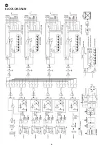
Page 6: ...EN 6 BLOCK DIAGRAM INPUT 1 INPUT 2 INPUT 3 INPUT 4 INPUT 5 Z2 Z3 Z4 Z1...
Page 12: ...EN 12 ES DIAGRAMA DE BLOQUES INPUT 1 INPUT 2 INPUT 3 INPUT 4 INPUT 5 Z2 Z3 Z4 Z1...
Page 24: ...24 DIAGRAMA DE BLOCOS INPUT 1 INPUT 2 INPUT 3 INPUT 4 INPUT 5 Z2 Z3 Z4 Z1...
Page 26: ......
Page 27: ......
Page 28: ...www fonestar com...


