


24
130
130
630
1260
1886
1730
1761
1090
2047
H
374
122
190
171
343
560
742
170
641
1062
203
4
3
2
1
474
190
171
342
122
235
535
741
630
630
274,5
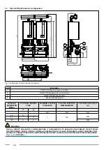
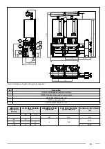
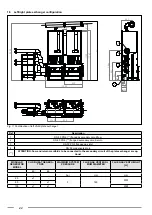
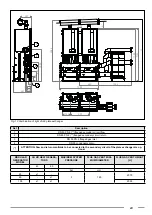
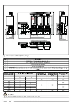
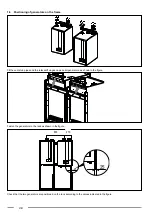
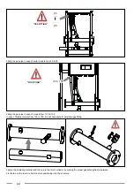
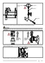
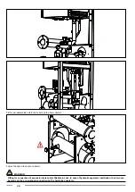
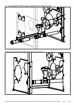
Fig. 13 Combination of left 85-120 plate exchanger
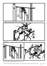
Ref
Description
1
DN 80 PN 6 (**) flanged secondary circuit flow
2
DN 80 PN 6 (**) flanged secondary circuit return
3
DN 50 PN 6 flanged gas inlet
4
DN 50 condensate drain
(**)
ATTENTION: flow and return manifolds to be connected to the secondary circuit of the plate exchanger are op
-
tional
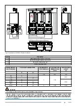
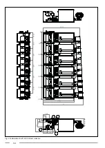
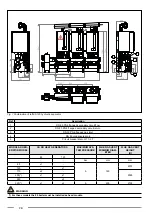
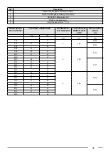
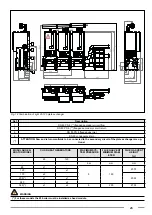
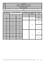
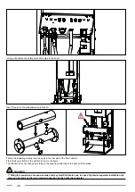
MODULAR GEN-
ERATOR MODEL
CH KR HEAT GENERATORS
MAXIMUM SYS-
TEM PRESSURE
FLUE GAS VENT
MINIMUM DIAM-
ETER
FLUE GAS VENT
HEIGHT
[H]
85
120
-
-
-
bar
mm
mm
85
x1
-
5
160
2075
120
-
x1
170
x2
-
2095
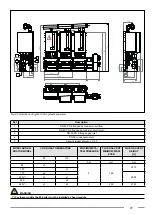
205(*)
x1
x1
240
-
x2
325(*)
x1
x2
5
200
2135
WARNING
(*) For these models the 85 boiler must be installed as head module.


