background image

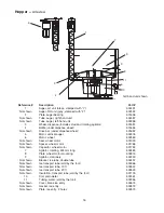
Reference #

Description

Part #

1

Transformer, 24V

502058

2

Relay, dispense

501826

3

Relay, auto fill

501826

4

Timer, auto fill (automatic fill units)

502471

5

Strip, terminal

502472

6

Tube, water dispense, stainless steel

502356

7

Bracket, water solenoid

502611

8

Fitting, outlet, 1/8" MPT x 3/8", compression

502562

9

Valve, solenoid, water

502243

10

Fitting, inlet, plastic, 1/4"  barb

502637

11

Tubing, water (sold by the foot)

502356

13

Switches (power and icemaker)

502209

14

Bracket, switch mounting, RH (power and icemaker)

502914

Not shown

Bracket, switch mounting, LH (power and icemaker)

502906

15

Chute, focus, clear plastic

502459

Not shown

Thermostat, bin level

501432

Not shown

Magnetic switch

502887

(1) one located under top cover
(2) two located under electrical component cover

Not shown

Magnets

502888

(2) two located on drain pan
(1) one located on top cover
(1) one located on rear cover

Electrical components

18

11

1

5

2

4 3 7

6

15

9

13

14

15

6

8

9

10

11

7

Summary of Contents for MU155N Series

Page 1: ...ool Ideas For Ice Management 209091R00 801 Church Lane PO Box D Easton PA 18044 610 252 7301 FAX 610 250 0696 www follettice com Following installation please forward this manual to the appropriate operations person Automatic load units with two icemakers Automatic load units with one icemaker ...

Page 2: ......

Page 3: ... procedures 6 Installing dispenser in counter 6 Installing remote icemaker 7 Start up 8 User Information 8 Cleaning Procedures 8 Disassembly for cleaning 10 Service information 11 Disassembly for service 11 Wiring diagrams 12 Dispenser troubleshooting guide 13 Replacement parts 14 Dispenser exterior 14 Dispense assembly 15 Hopper 16 Auger motor 17 Electrical components 18 2 ...

Page 4: ...00AR Condenser type A air cooled W water cooled Remote icemaker s capacity and refrigerant 400 400 lbs 181kg day R404A 800 800 lbs 363kg day R404A absence of manual fill unit N ice and water only no beverage rail or valves Approximate storage capacity in lbs Dispenser configuration U undercounter 3 Model Icemaker Dispenser number amperage amperage MU155NR400A W 11 0 amps 4 0 amps MU155NR800A W 11 ...

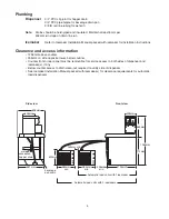
Page 5: ...er 305mm on side opposite tower below counter Counter front or rear panel must be removable for service access to both sides of dispenser and icemaker s if any Below counter access to drain clean out required on utility side of dispenser See Icemaker Installation Manual packed with icemaker s for clearance requirements for automatic load dispensers 4 Side view Front view 553mm 305mm 305mm 696mm 71...

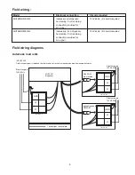
Page 6: ...e R400A W ice machine Junction box L1 L2 GND Electric supply 120V 60Hz optional second R400A W Automatic load units Field wiring diagrams Model Electrical connection Circuits required MU155NR400A W icemaker and dispenser 120V 60Hz 2 circuits required hard wiring Cord and plug connection provided for bin signal MU155NR800A W icemaker s and dispenser 120V 60Hz 3 circuits required hard wiring Cord an...

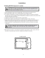
Page 7: ...alant Dow Corning RTV 732 or equivalent approximately 6mm in diameter around perimeter of dispenser where it meets counter and smooth sealant to a 4mm radius 7 Install a hard drain line maintaining at least a 6mm per 304mm run slope and insulate line to prevent condensation 8 Make electrical connections in accordance with applicable wiring diagrams provided as well as NEC and local codes Provide d...

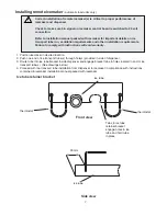
Page 8: ...d in icemaker installation manual packed with icemaker 7 Correct installation of remote icemaker s is critical to proper performance of icemaker and dispenser Check to make sure bin signal on icemaker control board is switched to 24 volt connection Refer to installation manual packed with icemaker for important details on ice transport tube run ventilation requirements and other installation requi...

Page 9: ...away from the dispenser As water freezes to the inside walls of the icemaker evaporator a rotating stainless steel auger removes ice and carries it to the top of the evaporator assembly where it is compressed and extruded through an outlet port The extruded ice is then pushed through the tube to the storage compartment of the dispenser A level fill circuit maximizes fill in the storage area by rot...

Page 10: ...ean out plug from drain line tee on side opposite dispense tower and let bath drain 7 Use a bottle brush to clean coil with Solution A then rinse and sanitize with Solution B 8 Reinstall clean out plug in drain line tee 9 Pour potable water into bath to submerge coil Putting unit back in service after quarterly cleaning 1 Reassemble components 2 For manual load units fill unit with an approved ice...

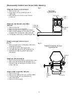
Page 11: ...l auger upward to clear auger tube 3 Lift auger tube upward to clear dispenser top 4 Slide tube and bearing plate through auger tube gasket Dispense wheel removal 1 Remove drain pan assembly and bin access cover 2 Remove center thumbnut and threaded rod on dispense wheel assembly and lift wheel out front access opening Auger motor assembly removal 1 Remove top cover 2 Remove one thumbnut on rear o...

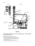
Page 12: ...el baffle plate under dispense wheel 3 Remove two screws holding wheel motor bracket on bin 4 Lift plate and motor up 5 Unplug electric quick disconnects from motor 6 Lift motor and mounting plate out front access opening 11 2 wheel motor baffle plate wheel motor mounting plate dispense wheel auger tube auger auger motor side view auger bearing plate stationary agitator rotating agitator front vie...

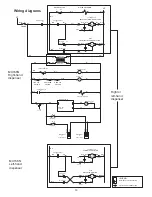
Page 13: ...HEEL Red M2 Blu M1 WATER SWITCH DISPENSE RELAY R1 Orn C NO WATER SOLENOID AUGER MOTOR TERMINAL STRIP CONNECTION PIN and SOCKET CONNECTION LEGEND CLOCKWISE ROTATION CLOCKWISE ROTATION MU155N Left hand dispenser Wht Orn Pur Wht Wht 7 1 R2 Orn 6 AUTOFILL 9 AUTOFILL R2 Pur 4 7 Pur L2 Wht R1 DISPENSE RELAY Orn Wht Blk Red Red Blu Blu Blk Red Red M2 WHEEL Blu Blu M1 Wht AUGER MOTOR PL2 1 PL2 2 PL2 3 PL3...

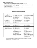
Page 14: ...ace switch 3 Replace transformer 4 Check pan and reseat 5 Replace switch 1 Check connections 2 Check linkage 3 Replace solenoid 1 Check connections 2 Check auger motor 3 Check run capacitor 1 Check connections 2 Check wheel motor 3 Check capacitor 1 Check switch and replace if necessary 2 Check switch and replace if necessary 3 Replace bin thermostat 4 Replace transformer 5 Refer to icemaker Opera...

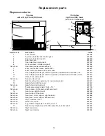
Page 15: ...includes label 502441 13 Splash shield right hand unit 502612 Not shown Splash shield left hand unit 502613 14 Thumbscrew splash shield 10 32 x 1 2 501100 Not shown Panel access right hand and left hand units 502907 16 Panel wrap right hand unit 502909 Not shown Panel wrap left hand unit 502908 Not shown Panel rear motor support right hand unit 502586 Not shown Panel rear motor support left hand u...

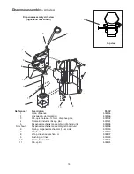
Page 16: ...lenoid includes linkage pin 501961 5 Dispense mechanism assembly right hand unit 502458 Not shown Dispense mechanism assembly left hand unit 502496 6 Spring dispense mechanism 1 per side 501950 7 Chute ice 502457 8 Wrap dispense mechanism 502607 9 Bushing Ni liners 501249 10 Screw 8 32 x 5 16 502625 11 Pin spring 502624 15 5 Dispense assembly side view top view 1 2 3 4 6 7 8 9 10 11 9 ...

Page 17: ...01333 Not shown Spacer wheel motor 501768 Not shown Capacitor wheel motor 501782 7 Agitator rotating 534mm long 502484 8 Plate wheel motor mounting 502615 9 Agitator stationery 502490 Not shown Bracket ice tube double tube 502497 Not shown Ice transport tube sold by the foot 500366 Not shown Ice transport tube 10 ft 502522 Not shown Ice transport tube 20 ft 502523 Not shown Insulation transport tu...

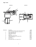
Page 18: ... 40p 502477 3 Sprocket 35 22T 5 8 bore 502478 4 Sprocket 35 12T 5 8 bore 502479 5 Drive shaft 502480 6 Bearing auger upper and lower 501314 7 Cover and bearing chain drive includes 501314 502912 8 Capacitor 25mf 270V 501550 9 Key Woodruff 502482 10 Washers thrust 4 501765 11 Mounting plate auger motor includes 501314 502913 Auger motor 7 6 1 8 4 3 2 11 10 5 side view top view 9 6 ...

Page 19: ...502637 11 Tubing water sold by the foot 502356 13 Switches power and icemaker 502209 14 Bracket switch mounting RH power and icemaker 502914 Not shown Bracket switch mounting LH power and icemaker 502906 15 Chute focus clear plastic 502459 Not shown Thermostat bin level 501432 Not shown Magnetic switch 502887 1 one located under top cover 2 two located under electrical component cover Not shown Ma...

Page 20: ...Cool Ideas For Ice Management 209091R00 4 02 801 Church Lane PO Box D Easton PA 18044 610 252 7301 FAX 610 250 0696 www follettice com ...

Reviews: