background image

14

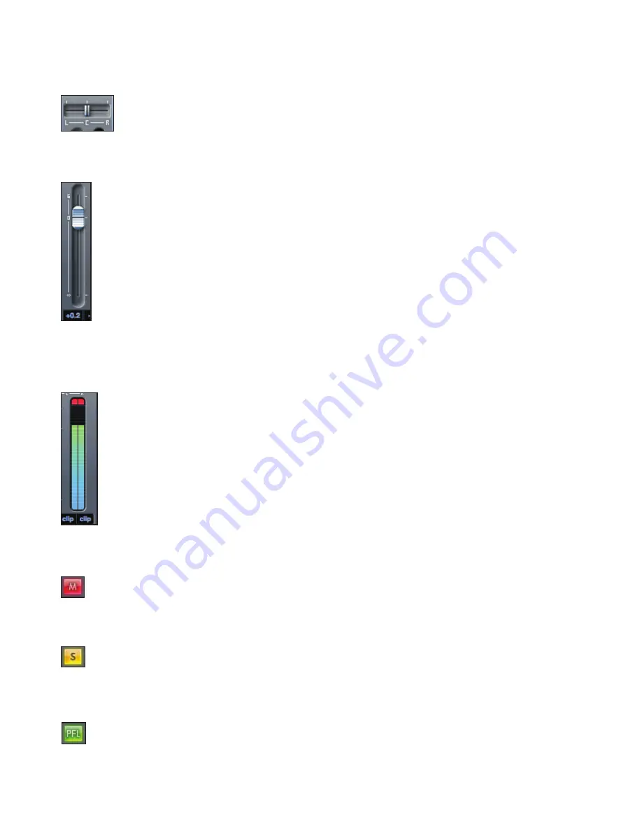
Pan slider  

 A Pan slider is used to position the audio signal anywhere between the left and right speakers.

Moving the horizontal slider from left to right will move the audio signal from left to right within the stereo field, i.e., 

the signal is faded between two audio outputs such as monitor L and R.


When used with a stereo track, the slider affects the audio signal such that when fully left, only the left channel is 

heard. When fully right, only the right channel is heard

Fader  


Use the fader to set the level of your audio signal for monitoring within the current mixer. 

Click the fader with your mouse and drag to any position. Double click on the fader to set it to 0.  

Fader range is from -∞ to +6dB with the current fader level displayed in the box below.  

Holding the Shift key whilst moving the fader allows for fine adjustment of fader levels. 


Meter 

The meter shows the signal level of the source input to the channel. The recent maximum signal level is displayed in the box below. 


The metering is always pre-fade, showing the level of the signal at the input. Therefore, the fader level has no effect on 

the metering. 

 There is a clip light at the top of the meter. If this red portion at the top of the meter lights up, then the signal level is too 

high. The signal level must be turned down by either using the gain knobs on the front panel for the analogue inputs, 

using the gain on the external devices connected to the digital inputs or using the gain within the DAW.

Once the gains are lowered, click on the red portion to reset the clip light.

Mute  

  Pressing this button mutes the signal. Red indicates that mute is active.  

Solo  

  Pressing this button solos the signal. The level of the fader will affect the level of the solo signal.  

  Yellow Indicates that solo is active.  

PFL (Pre-fade listen)  


  Pressing this button solos the signal and automatically routes it to monitor 1 and 2. The level of the soloed signal is pre- 


  fade (i.e. it will not be affected by the level of the fader). Green indicates that PFL is active.

Summary of Contents for Scarlett 18i6

Page 1: ...1 Scarlett 18i6 User Guide FA0521 01 ...

Page 2: ...en spilled or objects have fallen into the Scarlett 18i6 the Scarlett 18i6 has been exposed to rain or moisture does not operate normally or has been dropped WARNING To reduce the risk of fire or electric shock do not expose the Scarlett 18i6 to rain or moisture It is important that Scarlett 18i6 shall not be exposed to dripping or splashing and that no objects filled with liquids such as vases sh...

Page 3: ...dance with the instructions may cause harmful interference to radio communications However there is no guarantee that interference will not occur in a particular installation If this equipment does cause harmful interference to radio or television reception which can be determined by turning the equipment off and on the user is encouraged to try to correct the interference by one or more of the fo...

Page 4: ...rchitecture 10 Firmware Update 10 Scarlett MixControl 11 Pre amp section 12 Mixer section 12 Mixer tab 12 Input channel 13 Mix output channel 15 Routing section 16 Routing audio to the headphones 16 Routing presets 17 Monitor section 18 Device status section 20 Sample rate display 20 Sync source display 20 Sync status display 20 USB driver 20 Settings menu Windows only 21 ASIO buffer size 21 Strea...

Page 5: ...s are routed to the physical outputs for you to connect to an amp and speakers powered monitors headphones analogue digital mixer and any other studio equipment that you wish to use There are also connectors for sending and receiving MIDI The accompanying software application Scarlett MixControl provides further recording routing and monitoring options as well as the ability to control global hard...

Page 6: ...rlett 18i6 will use a significant amount of USB bandwidth the amount of data transferred via USB If connected to a USB hub other devices connected to the hub may affect the performance of Scarlett 18i6 For example if using a USB 2 0 hard drive for audio sample playback also transferring a large amount of data this should not be connected to the same USB hub as Scarlett 18i6 Therefore it is recomme...

Page 7: ... 2 x TRS jack sockets for monitor outputs 1 and 2 3 1 x Optical input socket for ADAT inputs 1 8 4 1 x USB 2 0 socket 5 2 x DIN5 MIDI input and output sockets 6 1 x 2 0mm DC power inlet socket use supplied power supply only 7 2 x RCA S PDIF input and output sockets Either 1 4 inch TRS balanced or TS unbalanced jack connectors can be used 2 5 4 3 1 6 7 ...

Page 8: ...ls 3 Channels 1 and 2 instrument LEDs 4 Phantom power switch with LED for mic inputs 1 2 5 Channels 1 to 8 signal and overload LEDs 6 Power LED lit when the unit receives power from the external power supply unit 7 USB Active LED lit when the unit connects to the USB driver 8 LKD Locked LED lit when the unit locks to its internal clock or to an external clock source 9 Monitor level control 10 Head...

Page 9: ... 18i6 6 Restart the computer 7 Once the installation is complete the computer OS should automatically select the Scarlett 18i6 as the default audio outputs To make sure this is the case On Windows 7 go to Start Control Panel Hardware and Sound Sound Manage Audio Devices Set Default Playback and Recording to Scarlett 18i6 Audio On Windows Vista go to Start Control Panel Hardware and Sound Sound Man...

Page 10: ...ws the input routing configuration HARDWARE IN DAW IN Analogue 1 8 1 8 S PDIF 1 2 RCA 9 10 ADAT 1 8 Optical 11 18 Note that for sample rates of 88 1kHz and 96kHz the ADAT channel count drops from eight to four channels Firmware Update When starting Scarlett MixControl for the first time a firmware update may be required Follow on screen instructions to complete the firmware update before being abl...

Page 11: ...ncy settings Windows only are available from Scarlett MixControl To open Scarlett MixControl Windows Start Programs Focusrite Scarlett MixControl Mac Open Finder Applications Scarlett MixControl This is how the Scarlett MixControl Graphical Interface will appear on your computer 1 Mixer 2 Selected Mix tab 3 Mixer Input channel 4 Selected Mix Output channel 5 Routing and pre amp section 6 Monitor s...

Page 12: ...ignal What is set up in the mixer section of Scarlett MixControl only affects what is heard in the outputs of the mix The recording levels that are sent to the DAW are therefore only affected by the input gain settings on the Scarlett 18i6 not the mixer The mixer section is useful for creating different simultaneous mixes For example the recording engineer may wish to provide a headphone monitor m...

Page 13: ...F and ADAT and DAW outputs are available When selecting a source on a stereo channel if an odd numbered input is chosen for the left channel the next even number input is auto selected for right and vice versa Note that if an input has already been taken it will be greyed out and cannot be selected again The input needs to be deselected from the track where it is already taken and then re selected...

Page 14: ...nput to the channel The recent maximum signal level is displayed in the box below The metering is always pre fade showing the level of the signal at the input Therefore the fader level has no effect on the metering There is a clip light at the top of the meter If this red portion at the top of the meter lights up then the signal level is too high The signal level must be turned down by either usin...

Page 15: ...the stereo version takes up two channels of the available total output channel count Note that when the solo button on an output channel is pressed that channel i e the whole mix is soloed and routed to Monitor outputs 1 and 2 This is a non latching button The current mix can be named by typing the desired name in the text field below the output channel The given name appears in the mix tab For ex...

Page 16: ...st of all available audio output sources The available sources include All inputs Analogue 1 8 S PDIF 1 2 ADAT 1 8 All DAW playback streams DAW 1 6 All mixes from the mixer Mix 1 6 If the mix has been named by clicking in the track name section see previous chapter then this name is displayed as the mix source name Note that the routing section is linked to the selection made for the output channe...

Page 17: ...monitors 1 2 and headphones All input channels must therefore be monitored from within the DAW application Zero Latency Tracking Zero Latency Tracking is used for the recording process It will automatically output Mix 1 and 2 to all the line outputs routing to the main monitors and to the headphones simultaneously Line inputs and DAW outputs must be set up in Mix 1 so that the monitor sources can ...

Page 18: ...itor section in Scarlett MixControl The output levels set up in the DAW are used to control digital output levels Each button can be set to one of three possible states Blue this output is controlled by the below monitor section Red this output is not controlled by the below monitor section and it is muted Grey this output is not controlled by the below monitor section and it is at full level To s...

Page 19: ...as indicated with a blue button The dB display below shows the current level to which the monitor knob is set Note that the front panel Monitor control affects only outputs 1 and 2 and is an additional volume control on top of the monitor level set in Scarlett MixControl software Dim switch Attenuates the output level by 18dB Mute switch Mutes the output Left mute switch Mutes the left output Righ...

Page 20: ... rate changes to prevent any undesirable side effects in your DAW Sync source display This sync source display shows the currently selected sync source To change the sync source click on the red sync source value and select S PDIF ADAT or Internal Sync status display The sync status display shows Locked when the Scarlett 18i6 has successfully locked to the specified Sync Source If No Lock is seen ...

Page 21: ...t MixControl set ups Save opens a File Save window allowing selection of a location into which your Scarlett MixControl set up can be saved Subsequent saves overwrite the original file Save As opens a File Save window allowing selection of a location into which your Scarlett MixControl set up can be saved Use this option if you want to keep your original saved set up and create a new one with a di...

Page 22: ...trument inputs inputs 1 and 2 Frequency response 20Hz 20kHz 0 1dB Gain range 13dB to 60dB THD N 0 004 measured with 0dBu input and 20Hz 22kHz bandpass filter Noise 87dBu 20Hz 22kHz bandpass filter Analogue audio outputs outputs 1 2 Two electronically balanced outputs Maximum output level 0dBFS 16dBu Frequency response 20Hz 20kHz 0 2dB THD N 0 001 0dBFS input 20Hz 22kHz bandpass filter Crosstalk ch...

Page 23: ...her I O One USB Type B connector Two standard 5 pin DIN MIDI connectors in and out DC power input connector for use with supplied universal input power supply Front Panel Indicators Eight 2 segment input meters 18 and 0dBFS Power indicator LKD lock indicator USB connected indicator Instrument input source selection LED for channels 1 and 2 Phantom power 48V switch and LED for inputs 1 and 2 Weight...

Page 24: ...24 ...

Reviews: