2019-09-30 FOCALSPEC User quide LCI1220-1620 v1.0
14/31
FocalSpec Oy • Elektroniikkatie 13, FI
-
90590 Oulu • www.focalspec.com
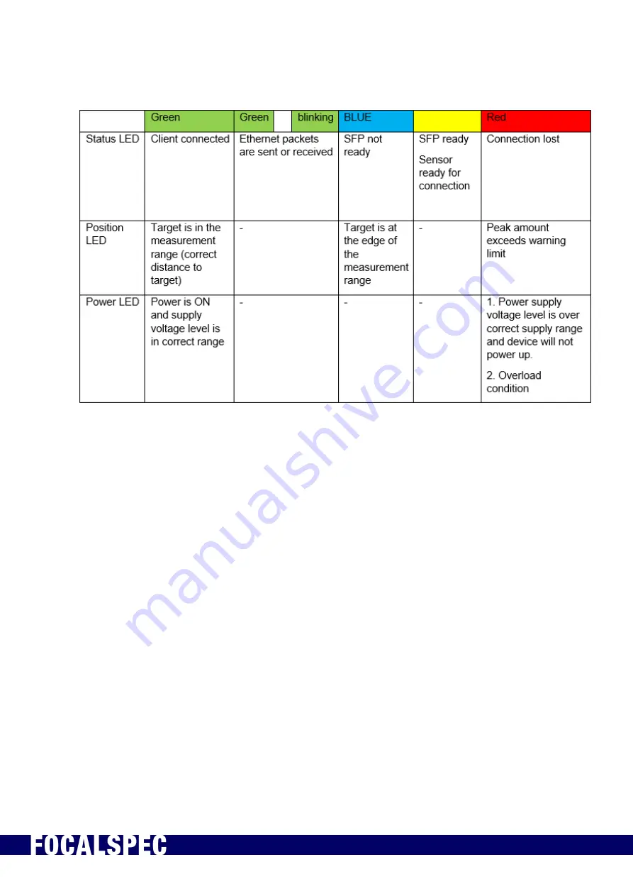
Table 2. Indicator LEDs
Page 1: ...FOCALSPEC LINE CONFOCAL SENSORS LCI1220 LCI1620 USER GUIDE Version 1 0...
Page 2: ...FOCALSPEC User quide LCI1220 1620 v1 0 1 31 FocalSpec Oy Elektroniikkatie 13 FI 90590 Oulu www focalspec com Version history Version Status Date Author Comments 1 0 Approved 30 9 2019 Esa Kalistaja Fi...
Page 3: ...4 3 Technical Data 5 4 Delivery Contents 5 5 Connecting to PC 6 6 Installation and Mounting 6 7 Handling Optical Cable and SFP Modules 9 7 1 General Instructions 9 7 2 Installing SFP Module and Optic...
Page 4: ...uences Caution A Caution statement alerts you to situations that can be potentially hazardous to you or cause damage to hardware firmware software or data Warning A Warning statement indicates conditi...
Page 5: ...and distances measurements measuring the tomography of transparent materials surface micro profile measurements and film thickness measurements Only use the sensor in such a way that in the case of m...
Page 6: ...58x113 mm Weight 19 21 kg Level of protection EN 80529 IP55 IP30 Z repeatability is the standard deviation of Z measurements using the FocalSpec target at the specified reference distance Maximum spee...
Page 7: ...A2 or four port DA4 model Figure 1 Example of two port Intel Ethernet Converged Network Adapter X520 DA2 Windows 10 64 bit is the recommended operating systems but sensors work also with Windows 7 6 I...
Page 8: ...2019 09 30 FOCALSPEC User quide LCI1220 1620 v1 0 7 31 FocalSpec Oy Elektroniikkatie 13 FI 90590 Oulu www focalspec com Figure 2 Installation and mounting of LCI1220...
Page 9: ...2019 09 30 FOCALSPEC User quide LCI1220 1620 v1 0 8 31 FocalSpec Oy Elektroniikkatie 13 FI 90590 Oulu www focalspec com Figure 3 Installation and mounting of LCI1620...
Page 10: ...side the optical fiber slots of the SFP module 7 1 General Instructions 1 When storing optical cables and SFP modules make sure the protective caps are attached 2 When the cables and SFP modules are i...
Page 11: ...SFP Module and Optical Cable Steps to install the optical cable and SFP module 1 Remove protective plug from SFP module 2 Remove protective caps from the other end of the optical cable Be sure not to...
Page 12: ...at by pushing the connector to the SFP module until it locks into place 6 Insert SFP module to the SFP card at PC step 4 Make sure the SFP module is positioned in the correct way CORRECT There should...
Page 13: ...n cable with Harting Power connector For input signals which can be used for synchronization purposes 10 pin PushPull type cables with Harting Signal Connectors is used The sensor communicates with PC...
Page 14: ...nnection is established The status LED blinks green when Ethernet packets are sent or received The position LED helps the user to find the correct distance to the target to measure A green light is sh...
Page 15: ...2019 09 30 FOCALSPEC User quide LCI1220 1620 v1 0 14 31 FocalSpec Oy Elektroniikkatie 13 FI 90590 Oulu www focalspec com Table 2 Indicator LEDs...
Page 16: ...w focalspec com 9 Input and Output Description Table 3 Power cable pinout Pin Color Name Description 1 24VDC 24 V 21 V 28 V 2 3 A 2 24VDC 3 GND Power Ground 4 Red ring Terminal Cable Shield Cable shie...
Page 17: ...te Input GND Common ground for inputs 2 Brown Input 1 Input 1 5V 24 V default encoder A input 3 Green Input 2 Input 2 5V 24 V default encoder disable input 4 Yellow Input 3 Input 3 5V 24 V default zer...
Page 18: ...Output Parameter Value Sensor Power supply voltage recommended 24VDC Power supply unit requirements PSU 24VDC 4A Input signal voltage operating range 3 5V 26V Input signal Maximum pulse rate 150 kHz...
Page 19: ...2019 09 30 FOCALSPEC User quide LCI1220 1620 v1 0 18 31 FocalSpec Oy Elektroniikkatie 13 FI 90590 Oulu www focalspec com Figure 11 Optical cable SFP module...
Page 20: ...ocalSpec Oy Elektroniikkatie 13 FI 90590 Oulu www focalspec com Figure 12 Example wiring for sensor connection NOTE 1 Connect the power cable ring terminal to system GND NOTE 2 Ensure that the sensor...
Page 21: ...sor keeps count of the trigger location internally and embeds this information for each frame B input of the encoder can be used as a disable signal On every rising edge of the encoder input signal A...
Page 22: ...solute Z value This way the set up is less sensitive to any variation over time like vibration or ambient condition changes 12 Preparing Measurement Setup To ensure the most favorable measurement cond...
Page 23: ...2019 09 30 FOCALSPEC User quide LCI1220 1620 v1 0 22 31 FocalSpec Oy Elektroniikkatie 13 FI 90590 Oulu www focalspec com Figure 15 Reference sample holders of LCI1220 left and LCI1620...
Page 24: ...s chapter gives instructions on how to set up the system with the sensor and a PC in order to show measurement profile Step Illustration Instructions 1 Lay down the sensor carefully on a table with Fo...
Page 25: ...www focalspec com 3 Remove dust caps from POWER I O 1 and Ethernet Power and I O caps are connected to sensor Ethernet cap is loose store it for possible future use 4 Dust caps removed from POWER I O...
Page 26: ...that power source voltage setting is the correct 24V Plug in 4 pin power connector Yellow marks indicate correct orientation 8 Remove dust cap from the optical Ethernet cable end store it for possibl...
Page 27: ...ng up takes about 30 seconds 11 Check that Jumbo Packet setting is 9014 Bytes 1 Click Start icon on the bottom left of the Windows task bar 2 Select Control Panel 3 Select Network and Sharing Center I...
Page 28: ...ically is selected as depicted on the left 4 Click OK 13 Double click setup exe on the USB drive and follow on screen instructions to install FocalSpec Software Development Kit If Windows asks you if...
Page 29: ...the sensor power wait until the power LED indicator is green Start FocalSpec GUI Example Application by double clicking the shortcut on desktop 15 The application controls are explained in FocalSpec...
Page 30: ...are sent by the sensor controller software b If there are no ARP packets the cause may be one of these i Firewall is enabled ii Network cables have not been properly attached Double check connections...
Page 31: ...ange LED Pulse Width s back to a more reasonable value To validate monitor Average Intensity text box which indicates if LED Pulse Width s is too low ok or too high 15 Support For further assistance p...